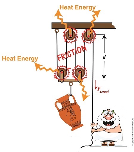
Last time we saw how the presence of friction reduces mechanical advantage in an engineering scenario utilizing a compound pulley. We also learned that the actual amount of effort, or force, required to lift an object is a combination of the portion of the force which is hampered by friction and an idealized scenario which is friction-free. Today we’ll begin our exploration into how frictionresults in reduced work input, manifested as heat energy lost to the environment. The net result is that work input does not equal work output and some of Mr. Toga’s labor is unproductive.
Friction Results in Heat and Lost Work Within a Compound Pulley
In a past blog, we showed how the actual force required to lift our urn is a combination of F, an ideal friction-free work effort by Mr. Toga, and FF , the extra force he must exert to overcome friction present in the wheels,
FActual =F + FF (1)
Mr. Toga is clearly working to lift his turn, and generally speaking his work effort, WI, is defined as the force he employs multiplied by the length, d, of rope that he pulls out of the compound pulley during lifting. Mathematically that is,
WI = FActual × d (2)
To see what happens when friction enters the picture, we’ll first substitute equation (1) into equation (2) to get WI in terms of F and FF,
WI = (F + FF ) × d (3)
Multiplying through by d, equation (3) becomes,
WI = (F ×d )+ (FF × d) (4)
In equation (4) WI is divided into two terms. Next time we’ll see how one of these terms is beneficial to our lifting scenario, while the other is not.
The presence of friction in mechanical designs is as guaranteed as conflict in a good movie, and engineers inevitably must deal with the conflicts friction produces within their mechanical designs. But unlike a good movie, where conflict presents a positive, engaging force, friction’s presence in pulleys results only in impediment, wasting energy and reducingmechanical advantage. We’ll investigate the math behind this phenomenon in today’s blog.
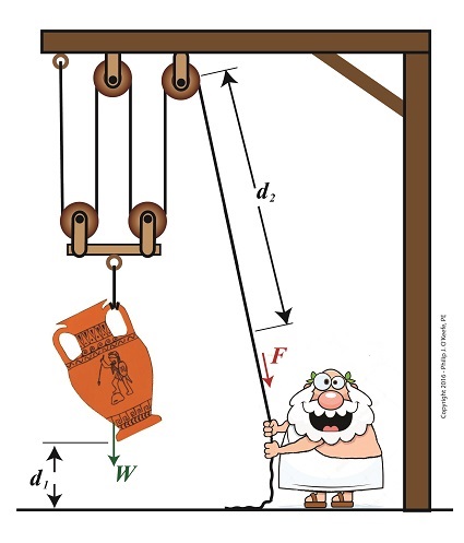
where d2 is the is the length of rope Mr. Toga extracts from the pulley in order to lift his urn a distance d1 above the ground. Engineers refer to this idealized frictionless scenario as an ideal mechanical advantage, IMA, so equation (1) becomes,
IMA = d2 ÷ d1 (2)
We also learned that in the idealized situation mechanical advantage is the ratio of the urn’s weight force, W, to the force exerted by Mr. Toga, F, as shown in the following equation. See our past blog for a refresher on how this ratio is developed.
IMA = W ÷ F (3)
In reality, friction exists between a pulley’s moving parts, namely, its wheels and the rope threaded through them. In fact, the more pulleys we add, the more friction increases.
The actual amount of lifting force required to lift an object is a combination of FF , the friction-filled force, and F, the idealized friction-free force. The result is FActual as shown here,
FActual =F + FF (4)
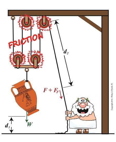
The real world scenario in which friction is present is known within the engineering profession as actual mechanical advantage, AMA, which is equal to,
AMA = W ÷ FActual (5)
To see how AMA is affected by friction force FF, let’s substitute equation (4) into equation (5),
AMA = W ÷(F + FF) (6)
With the presence of FF in equation (6), W gets divided by the sum of F and FF . This results in a smaller number than IMA, which was computed in equation (3). In other words, frictionreduces the actualmechanical advantage of the compound pulley.
Next time we’ll see how the presence of FF translates into lost work effort in the compound pulley, thus creating an inequality between the work input, WI and work output WO.
In our last blog we saw how adding extra pulleys resulted in mechanical advantagebeing doubled, which translates to a 50% decreased lifting effort over a previous scenario.Pulleys are engineering marvels that make our lives easier. Theoretically, the more pulleys you add to a compound pulley arrangement, the greater the mechanical advantage — up to a point. Eventually you’d encounter undesirable tradeoffs. We’ll examine those tradeoffs, but before we do we’ll need to revisit the engineering principle of work and see how it applies to compound pulleys as a work input-output device.
Pulleys as a Work Input-Outut Device
The compound pulley arrangement shown includes distance notations, d1 and d2. Their inclusion allows us to see it as a workinput-output device.Work is input by Mr. Toga, we’ll call that WI, when he pulls his end of the rope using his bicep force, F. In response to his efforts, workis output by the compound pulley when the urn’s weight, W, is lifted off the ground against the pull of gravity. We’ll call that work outputWO.
In a previous blog we defined work as a factor of force multiplied by distance. Using that notation, when Mr. Toga exerts a force F to pull the rope a distance d2 , his work input is expressed as,
WI = F × d2
When the compound pulley lifts the urn a distance d1 above the ground against gravity, its work output is expressed as,
WO = W × d1
Next time we’ll compare our pulley’swork input to output to develop a relationship between d1 and d2. This relationship will illustrate the first undesirable tradeoff of adding too many pulleys.
Last time we saw how compound pulleys within a dynamic lifting scenario result in increasedmechanical advantage to the lifter, mechanical advantage being an engineering phenomenon that makes lifting weights easier. Today we’ll see how the mechanical advantageincreases when more fixed and movable pulleys are added to the compound pulley arrangement we’ve been working with.
More Pulleys Increase Mechanical Advantage
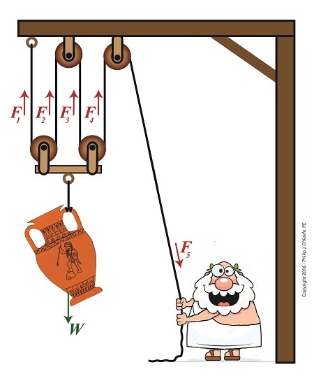
The image shows a more complex compound pulley than the one we previously worked with. To determine the mechanical advantage of this pulley, we need to determine the force, F5, Mr. Toga exerts to hold up the urn.
The urn is directly supported by four equally spaced rope sections with tension forces F1, F2, F3, and F4. The weight of the urn, W, is distributed equally along the rope, and each section bears one quarter of the load. Mathematically this is represented by,
F1 = F2 = F3 = F4 = W ÷4
If the urn’s weight wasn’t distributed equally, the bar directly above it would tilt. This tilting would continue until equilibrium was eventually established, at which point all rope sections would equally support the urn’s weight.
Because the urn’s weight is equally distributed along a single rope that’s threaded through the entire pulley arrangement, the rope rule, as I call it, applies. The rule posits that if we know the tension in one section of rope, we know the tension in all rope sections, including the one Mr. Toga is holding onto. Therefore,
F1 = F2 = F3 = F4 = F5 = W ÷4
Stated another way, the force, F5 , Mr. Toga must exert to keep the urn suspended is equal to the weight force supported by each section of rope, or one quarter the total weight of the urn, represented by,
F5 = W ÷4
If the urn weighs 40 pounds, Mr. Toga need only exert 10 pounds of bicep force to keep it suspended, and today’s compound pulley provides him with a mechanical advantage, MA, of,
MA = W ÷ F5
MA =W ÷ (W ÷ 4)
MA = 4
It’s clear that adding the two extra pulleys results in a greater benefit to the man doing the lifting, decreasing his former weight bearing load by 50%. If we added even more pulleys, we’d continue to increase his mechanical advantage, and he’d be able to lift far heavier loads with a minimal of effort. Is there any end to this mechanical advantage? No, but there are undesirable tradeoffs. We’ll see that next time.
In this blog series on pulleys we’ve gone from discussing the simple pulley to the improved simple pulley to an introduction to the complex world of compound pulleys, where we began with a static representation. We’ve used the engineering tool of a free body diagram to help us understand things along the way, and today we’ll introduce another tool to prepare us for our later analysis of dynamic compound pulleys. The tool we’re introducing today is the engineering concept of mechanical advantage, MA, as it applies to a compound pulley scenario.
The term mechanical advantage is used to describe the measure of force amplification achieved when humans use tools such as crowbars, pliers and the like to make the work of prying, lifting, pulling, bending, and cutting things easier. Let’s see how it comes into play in our lifting scenario.
During our previous analysis of the simple pulley, we discovered that in order to keep the urn suspended, Mr. Toga had to employ personal effort, or force, equal to the entire weight of the urn.
F = W (1)
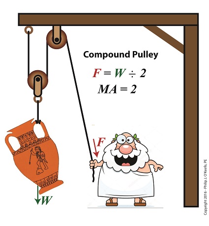
By comparison, our earlier discussion on the static compound pulley revealed that our Grecian friend need only exert an amount of personal force equal to 1/2 the suspended urn’s weight to keep it in its mid-air position. The use of a compound pulley had effectively improved his ability to suspend the urn by a factor of 2. Mathematically, this relationship is demonstrated by,
F = W ÷ 2 (2)
The factor of 2 in equation (2) represents the mechanical advantage Mr. Toga realizes by making use of a compound pulley. It’s the ratio of the urn’s weight force, W, to the employed force, F. This is represented mathematically as,
MA =W÷F (3)
Substituting equation (2) into equation (3) we arrive at the mechanical advantage he enjoys by making use of a compound pulley,
MA =W÷ (W ÷ 2) = 2 (4)
Mechanical Advantage of a Compound Pulley
Next time we’ll apply what we’ve learned about mechanical advantage to a compound pulley used in a dynamic lifting scenario.
When acting as an engineering expert I’m often called upon to investigate incidents where energy converts from one form to another, a phenomenon that James Prescott Joule observed when he built his apparatus and performed his experiments with electricity. Today we’ll apply Joule’s findings to our own experiment with a coffee mug when we convert its kinetic energyinto electrical energy and see how the units used to express that energy also change.
We had previously calculated the kinetic energy contained within our falling coffee mug to be 4.9 kg • meter2/second2, also known as 4.9 Joules of energy, by using de Coriolis’ Kinetic Energy Formula. Now most of us don’t speak in terms of Joules of energy, but that’s easily addressed. As we learned in a previous blog on The Law of Conservation of Energy, all forms of energy are equivalent and energy can be converted from one form to another, and when it does, the unit of energy used to express it also changes.
Let’s say we want to put our mug’s 4.9 Joules of kinetic energy to good use and power an electric light bulb. First we must first find a way of converting the mug’s kinetic energy into electrical energy. To do so, we’ll combine Joule’s apparatus with his dynamo, and connect the mug to this hybrid device with a string.
Converting Kinetic Energy to Electrical Energy
As the mug falls its weight tugs on the string, causing the winding drum to rotate. When the drum rotates, the dynamo’s magnet spins, creating electrical energy. That’s right, all that’s required to produce electricity is a spinning magnet and coils of wire, as explained in my previous blog, Coal Power Plant Fundamentals – The Generator.
Now we’ll connect a 5 Watt bulb to the dynamo’s external wires. The Watt is a unit of electrical energy named in honor of James Watt, a pioneer in the development of steam engines in the late 18th Century.
Now it just so happens that 1 Watt of electricity is equal to 1 Joule of energy per a specified period of time, say a second. This relationship is expressed as Watt • second. Stated another way, 4.9 Joules converts to 4.9 Watt • seconds of electrical energy. Let’s see how long we can keep that 5 Watt bulb lit with this amount of energy. Mathematically this is expressed as,
This means that if the mug’s kinetic energy was totally converted into electrical energy, it would provide enough power to light a 5 Watt bulb for almost 1 second.
Next time we’ll see what happens to the 4.9 Joules of kinetic energy in our coffee mug when it hits the floor and becomes yet another form of energy.
Last time we learned that gear trains are torque converters, and we developed a torque ratio equation which mathematically ties the two gears in a gear train together. That equation is:
T1 ÷ T2 = D1 ÷ D2
Engineers typically use this equation knowing only the value for T2, the torque required to properly drive a piece of machinery. That knowledge is acquired through trial testing during the developmental phase of manufacturing.
Once T2 is known, a stock motor is selected from a catalog with a torque value T1 which closely approximates that of the required torque, T2. Then calculations are performed and lab tests are run to determine the driving and driven gear sizes, D1 and D2 which will enable the gear train to convert T1 into the required value of T2. This series of operations are often a time consuming and complex process.
To simplify things for the purpose of our example, we’ll say we’ve been provided with all values required for our equation, except one, the value of T2. In other words, we’ll be doing things in a somewhat reverse order, because our objective is simply to see how a gear train converts a known torque T1 into a higher torque T2.
We’ll begin by considering the gear train illustration above. For our purposes it’s situated between an electric motor and the lathe it’s powering. The motor exerts a torque of 200 inch pounds upon the driving gear shaft of the lathe, a torque value that’s typical for a mid sized motor of about 5 horsepower. As-is, this motor is unable to properly drive the lathe, which is being used to cut steel bars. We know this because lab testing has shown that the lathe requires at least 275 inch pounds of torque in order to operate properly.
Will the gears on our gear train be able to provide the required torque? We’ll find out next time when we insert values into our equation and run calculations.
Last time we introduced the mathematical formula for torque, which is most simply defined as a measure of how much a force acting upon an object causes that object to rotate around a pivot point. When manipulated, torque can produce a mechanical advantage in gear trains and tools, which we’ll see later. The formula is:
Torque = Distance × Force × sin(ϴ)
We learned that the factors Distance and Force are vectors, and sin(ϴ) is a trigonometric function of the angle ϴ which is formedbetween their two vectors. Let’s return to our wrench example and see how the torque formula works.
Vectors have both a magnitude, that is, a size or extent, and a direction, and they are typically represented in physics and engineering problems by straight arrows. In our illustration the vector for distance is represented by an orange arrow, while the vector for force is represented by a red arrow. The orange distance vector has a magnitude of 6 inches, while the red force vector has a magnitude of 10 pounds, which is being supplied by the user’s arm muscle manipulating the nut. That muscle force follows a path from the arm to the pivot point located at the center of the nut, a distance of 6 inches.
Vector arrows point in a specific direction, a direction which is indicative of the way in which the vectors’ magnitudes — in our case inches of distance vs. pounds of force — are oriented with respect to one another. In our illustration the orange distance vector points away from the pivot point. This is according to engineering and physics convention, which dictates that, when a force vector is acting upon an object to produce a torque, the distance vector always points from the object’s pivot point to the line of force associated with the force vector. The angle, ϴ, that is formed between the two vectors in our example is 90 degrees, as measured by any common, ordinary protractor.
Next we must determine the trigonometric value for sin(ϴ). This is easily accomplished by simply entering “90” into our calculator, then pressing the sin button. An interesting fact is that when the angle ϴ ranges anywhere between 0 and 90 degrees, the values for sin(ϴ) always range between 0 and 1. To see this in action enter any number between 0 and 90 into a scientific calculator, then press the sin button.
For our angle of 90 degrees we find that,
sin(90) = 1
Thus the formula for torque in our example, because the sin(ϴ) is equal to 1, simply becomes the product of the magnitudes of the Distance and Force vectors:
Torque = Distance × Force × sin(90)
Torque = Distance × Force × 1
Torque = Distance × Force
Next time we’ll insert numerical values into the equation and see how easily torque can be manipulated.
Last time we introduced a physics concept known as torque and how it, together with modified gear ratios, can produce a mechanical advantage in devices whose motors utilize gear trains. Now we’ll familiarize ourselves with torque’s mathematical formula, which involves some terminology, symbols, and concepts which you may not be familiar with, among them, vectors, and sin(ϴ).
Torque = Distance × Force × sin(ϴ)
In this formula, Distance and Force are both vectors. Generally speaking, a vector is a quantity that has both a magnitude — that is, any measured quantity associated with a vector, whether that be measured in pounds or inches or any other unit of measurement — and a direction. Vectors are typically represented graphically in engineering and physics illustrations by pointing arrows. The arrows are indicative of the directionality of the magnitudes involved.
Sin(ϴ), pronounced sine thay-tah, is a function found within a field of mathematics known as trigonometry , which concerns itself with the lengths and angles of triangles. ϴ, or thay-tah, is a Greek symbol used to represent the angle present between the Force and Distance vectors as they interact to create torque. The value of sin(ϴ) depends upon the number of degrees in the angle ϴ. Sin(ϴ) can be found by measuring the angle ϴ, entering its value into a scientific calculator, and pressing the Sin button.
We’ll dive into the math behind the vectors next time, when we return to our wrench and nut example and apply vector force quantities.