Last time, we learned how a solenoid valve operates to create different compressed air flow paths through passageways within its valve body. These different air flow paths are created by opening and closing an electrical switch to de-energize and energize a solenoid mounted on the valve body. Now let’s see how engineers use a solenoid valve in a food manufacturing plant to move a depositor’spneumatic actuator piston back and forth with compressed air pressure.
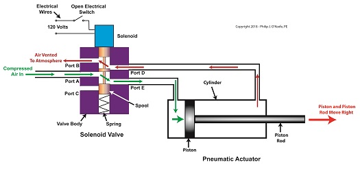
Consider the pneumatic actuator on the depositor’s scotch yoke. With the solenoid valve’s electrical switch opened, the valve’s spool is pushed up in the valve body by a spring to create air flow paths between Ports A and E and Ports D and B. If compressed air is fed into Port A and the left side of the pneumatic actuator’s cylinder is connected to Port E, then the air pressure moves the actuator’s piston to the right. But, for the actuator piston to move freely to the right, the right side of the cylinder is connected to Port D on the valve body. As the piston moves to the right, it forces air out of the right side of the cylinder, through Port D, through the valve body, and out through Port B to be vented to the atmosphere.
The De-energized Solenoid Valve Operates a Pneumatic Actuator
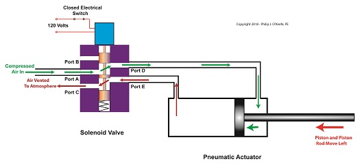
With the solenoid valve’s electrical switch closed, the spool is pushed down in the valve body by the solenoid, to create air flow paths between Ports A and D and Ports E and C. If compressed air is fed into Port A and the right side of the pneumatic actuator’s cylinder is connected to Port D, then the air pressure moves the actuator’s piston to the left. But, for the actuator piston to move freely to the left, the left side of the cylinder is connected to Port E. As the piston moves left, air is forced out of the left side of the cylinder, through Port E, and vented to the atmosphere through Port C.
The Energized Solenoid Valve Operates a Pneumatic Actuator
So, in review, opening the solenoid valve’s electrical switch causes the pneumatic actuator piston to move right. Closing the switch causes the piston to move left. But there is a problem with this setup. Operating an electrical switch by hand to deposit jelly filling on thousands of pastries can get tiring after a while. Next time, we’ll see how the valve’s solenoid can be automatically turned on and off by an industrial control system.
So far in this series of articles, we have talked about pneumatic actuators that move jelly filling through a depositor on a pastry production line in a food manufacturing plant. These actuators have pistons with piston rods that create linear motion. The direction of this motion depends on which side compressed air is admitted to the piston inside the actuator. Now, let’s begin discussing a device known to engineers as a solenoid valve. These valves are used to selectively admit compressed air to either side of the pneumatic actuator’s piston, and thus, change the direction of the actuator’s linear motion.
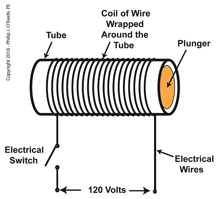
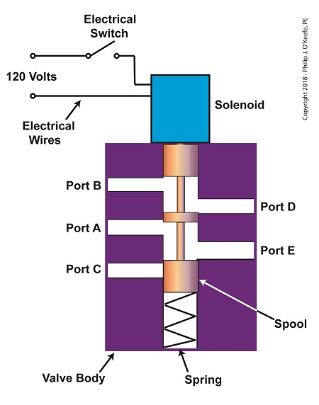
As a solenoid valve’s name implies, a key component is a solenoid. A solenoid consists of a tube, having a coil of wire wrapped around its exterior. Electrical wires extend from the coil to an electrical switch and a voltage supply of, for example, 120 Volts. Inside the tube, there is a steel plunger that is free to move. When the switch is open, the coil is de-energized. That is, no electric current flows from the voltage supply through the coil of wire.
A De-Energized Solenoid
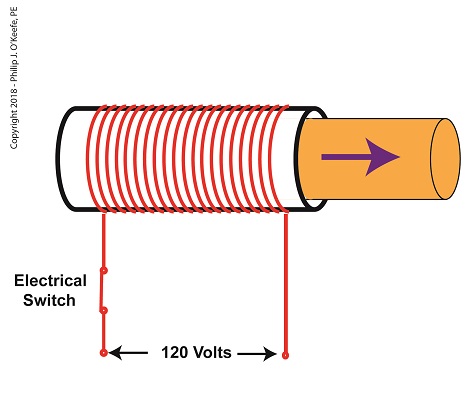
When the electrical switch is closed, the coil becomes energized. As electrical current flows through the coil, a magnetic field is created in the tube. This field forces the steel plunger out of the tube. The magnetic field and force on the plunger remain as long as the switch is closed.
An Energized Solenoid
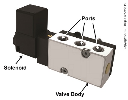
A solenoid valve consists of a solenoid that is attached to a metal valve body. The solenoid is typically enclosed in a plastic or metal housing. The valve body contains various ports. The ports are threaded holes for the connection of compressed air pipes.
A Solenoid Valve
The solenoid’s plunger is attached to spool in the valve body. The spool is free to move within the valve body past passage ways extending from the ports. In the following illustration, the solenoid valve contains five ports, designated A through E.
The Solenoid Valve’s Components
Next time we’ll see how the five port solenoid valve operates to create different compressed air flow paths between its ports.
Last time we learned that a fruit jelly depositor in a food manufacturing plant is an example of a positive displacement pump at work. Today we’ll see how pieces of equipment on the depositor, known as a pneumatic actuators, work. Pneumatic actuators do not come in contact with the jelly flowing through the depositor. In other words, no jelly flows through the actuators. The jelly only flows through the transfer valve and positive displacement pump as we saw last time. The pump and valve can’t move by themselves. So, they need some device to set them in motion. That’s where the pneumatic actuators come into play. They impart movement to the pump and transfer valve to get the jelly flowing from the hopper and down through the nozzle and onto the pastry.
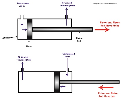
A pneumatic actuator is a device that operates using compressed air. Compressed air, from an external air compressor, enters into a tube in the actuator known as a cylinder. Inside the cylinder is a piston that can move along the length of the tube. Attached to the piston is a piston rod which extends to the outside of the cylinder.
When compressed air is introduced into the cylinder on the left side of the piston, it forces the piston and piston rod to move towards the right side of the cylinder. But, air must be vented out to atmosphere from the right side of the piston for this movement to occur. If no venting took place, trapped air to the right of the piston will get squeezed between the piston and the right end of the cylinder. When the air gets squeezed, it becomes pressurized. The pressure will impede the movement of the piston.
Likewise, when compressed air is introduced into the cylinder on the right side of the piston, it forces the piston and piston rod to move towards the left side of the cylinder.
The Depositor’s Pneumatic Actuator
So, depending on which end compressed air is admitted to the pneumatic actuator’s cylinder, the piston rod will move to the left or the right. In engineering terms, the actuator imparts linear motion to machines. In other words, the piston rod moves back and forth in a straight line.
Next time, we’ll see how the pneumatic actuator is connected to the depositor’s pump to impart the linear motion that draws jelly from the supply hopper and sends it streaming out of the nozzle onto a passing pastry.
Our last blog introduced a project I oversaw while acting as a design engineer in a food manufacturing plant. The objective was to deposit fruit jelly into raw pastry dough as it whizzed along a production line conveyor belt before being sent off for baking. A special piece of equipment known as a depositor would be required to meet this challenge, and we’ll take a look at how one functions today. In fact, a jelly depositor acts very much as a human heart, as they’re both examples of positive displacement pumps.
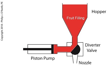
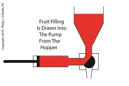
A depositor is a device specifically made for the food industry. It consists of a hopper to hold the product to be deposited, in this case fruit jelly, which is discharged by the hopper into a rotating diverter valve and then on to a positive displacementpiston pump. See below.
A Jelly Depositor is a Positive Displacement Pump
When the diverter valve rotates, a passageway opens to allow jelly to flow from the hopper into the piston pump. A pneumatic actuator, a device we’ll discuss in more depth next time, moves the pump’s piston to the left, away from the diverter valve, which allows the filling to be released into the pump from the hopper. At the end of the piston’s travel a set quantity of fruit jelly filling is drawn into the pump’s housing, just enough to fill one pastry. See below.
The Depositor Draws Filling Into The Pump
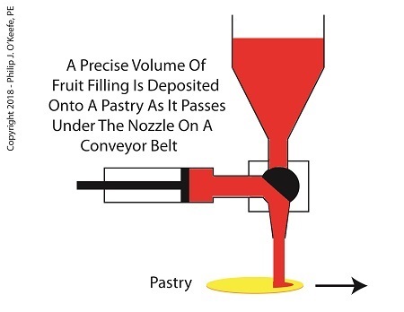
When the diverter valve rotates in the opposite direction, a passageway opens inside the valve that allows jelly filling to move from the pump to the nozzle. As the piston moves back toward the diverter valve the filling is forced out of the pump, through the nozzle, and into the pastry dough. The pump’s piston moves back and forth, that is, away from and then towards the transfer valve, ushering a set quantity of jelly filling through the mechanism each time. See below.
The Depositor Deposits The Filling
Now that we know how the depositor works, next time we’ll discuss the pneumatic actuator’s role in the filling process.
Last time we learned that the human heart functions as the greatest of all positive displacement pumps, moving a set quantity of blood through it at precise intervals during its operating cycle. Today we’ll begin our exploration into how positive displacement pumps are used in industry, specifically within a food manufacturing plant.
At one point in my career I was employed as a design engineer in a food manufacturing plant. The plant was owned by the leading manufacturer of bakery products in the United States, responsible for supplying restaurants, bakeries, and grocery stores with finished and partially finished pastry goods that they would then resell. The plant produced vast amounts of puff pastry dough products, all of which were formed and filled with various fillings while zipping along on a production line conveyor belt. One of the products was a fruit filled pastry in which the belt moved so quickly, depositing fruit fillings into the dough by hand would be impossible, resulting in a frenzied mess similar to what Lucy encountered when she worked in a candy factory.
Clearly, an automated machine would work better in this and other scenarios. We’ll see how one known as a depositor functions on a food pastry line next time.
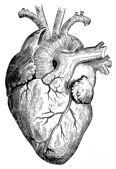
We couldn’t do without pumps. They serve up water from the tap, circulate our car’s coolant, and the master of all pumps, the human heart, keeps us alive. Pumps are essential in countless areas of our lives, and they’re of two major types, positive displacement or centrifugal. We’ll start our discussion with a focus on positive displacement pumps. Our hearts belong to this category.
Master of All Pumps, the Human Heart
As their name implies, positive displacement pumps displace, that is to say they move or circulate, a set quantity of liquid with each operating cycle. Your heart moves 2 to 3 ounces of blood with every heartbeat and up to 2,000 gallons of blood per day!
Next week we’ll introduce an industrial application for a positive displacement pump when we install one in a food manufacturing plant. You didn’t think those jelly pastries filled themselves, did you?
We’ve been discussing hurtles which must be jumped in order for an inventor’s creation to be considered for a patent. Federal statutes, namely 35 USC § 101, define the bases of patentability, including providing definitions on key terms, such as what constitutes a machine, an article of manufacture, and a composition of matter. Today we’ll wrap up our discussion on determining patent eligibility when we explore the final hurtle by defining process.
To get an understanding of what is meant by process, we must look to the lawsuit of Gottschalk v. Benson, a case involving patentability of a mathematical algorithm within a computer program. In this case the US Supreme Court held that a process is a series of steps or operations that transform substances or came about by way of a newly invented machine.
Based on the Court’s definition, a process can be many things, from a production line that transforms corn into corn chips within a food manufacturing plant to a mathematical algorithm running within software on the platform of a newly devised type of computer. However, the term usually pertains to a series of operations or steps, most frequently manufacturing in nature, where physical substances are transformed into useful products, that is, they possess the quality of utility, as discussed earlier in this blog series. A “physical substance” is anything of a physical nature existing on our planet.
Before I end this series I’d like to mention that under 35 USC § 101 an invention can be eligible for a patent if it makes a useful and beneficial improvement to an existing machine, article of manufacture, composition of matter, or process. That is to say, something may have already been patented which performs a specific function, but if that is improved upon in any significant way, it may receive a new patent.
For example, suppose an improved process for manufacturing food products was developed by adding additional steps to an existing patented process. If this improvement results in benefits such as lowered production costs, increased production rate, or reduced health risks to consumers, then this improved process may be eligible for a patent under 35 USC § 101.
Next time we’ll begin an exploration of the growing presence of 3D animations within the courtroom, specifically how they bring static 2D patent drawings to life.
Imagine having freshly baked pastries available to you all day long, every day, while at work. I’m not talking about someone bringing in a box of donuts to share, I’m talking about baked goods on a massive scale. This is what I experienced in one of my design engineering positions within the food industry. These baked goods constituted the articles of manufacture of the food plant, and they presented a constant temptation to me.
Just what constitutes an article of manufacture is another aspect of the second hurtle which must be passed to determine patent eligibility. It is addressed under federal statutes governing the same, 35 USC § 101, and is contained within the same area as the discussion of what constitutes a machine, a subject we took up previously in this series.
Why bother defining articles of manufacture? Well, while hearing the patent case of Diamond v. Chakrabarty regarding genetically engineered bacterium capable of eating crude oil, the US Supreme Court saw fit to define the term so as to resolve a conflict between the inventor and the patent office as to whether a living organism could be patented.
The net result was the Court declared that in order to be deemed a patentable article of manufacture the object must be produced from either raw or man-made materials by either hand labor or machinery and must take on “new forms, qualities, properties, or combinations” that would not naturally occur without human intervention. In other words, a creation process must take place and something which did not previously exist must be caused to exist.
The court’s definition of articles of manufacture encompasses an incredible array of products, much too vast to enumerate here. Suffice it to say that the defining characteristic is that if it should consist of two or more parts, there is no interaction between the parts, otherwise it could be categorized as a machine. In other words, the relationship between their parts is static, unmoving. An example would be a hammer. It’s made up of two parts, a steel head and wooden handle. These parts are firmly attached to one another, so they act as one.
Next time we’ll continue our discussion on the second hurtle presented by 35 USC § 101, where we’ll discuss what is meant by composition of matter.
___________________________________________
My daughter’s boy friend stayed for dinner recently and was impressed with our after-dinner cleanup. He watched as each of us carried out our individual assigned tasks, my wife putting away leftovers and condiments, my daughter rinsing and stacking plates into the dishwasher, and me at the sink hand washing. To him we seemed a model of efficiency. It didn’t take long to return the kitchen to its usual state of pristine evening cleanliness. “Our kitchen is always a mess,” he complained, “probably because we’re so disorganized.”
You can imagine what would happen if a food manufacturing plant operated like a disorganized household kitchen. Although employees may know they are responsible for delivering safe products to consumers, without the right procedures in place an unsafe chaotic mess may result. To get everyone moving in the right direction we look to guidelines established in HACCP Design Principle No. 6.
Principle 6: Establish procedures for ensuring the HACCP system is working as intended. – In large part this Principle acts as a report card. It follows up on the guidelines established in Principles l through 5, organizing activities into written procedures.
For example, design engineers must routinely analyze important identified stages within a design project, then write procedures, that is, a step-by-step instruction guide, which encompasses them. In this way personnel involved in the design process make best use of the safeguards put in place by HACCP Design Principles 1 through 5. These steps include things like preparing design proposals, analyzing risks and hazards, creating preliminary designs, conducting design reviews, building prototype equipment and tooling, running tests, collecting test data, and analyzing test results. For each step, responsibilities of key individuals involved must be clearly defined and sequentially ordered.
But writing department procedures is only part of Principle 6. Procedures are no good if they’re just thrown into a file cabinet and no one ever looks at them. What good are guidelines without a full understanding of how to use them? Training may be necessary, and management must decide what form that educational process takes to be most effective.
Engineering management must verify that established procedures are adequate to the task. This typically involves taking a hard look at finished design projects and checking critical factors. Was an adequate risk analysis performed? Were sufficient critical control points established and critical limits monitored for effectiveness?
Next time we’ll wrap up our discussion on HACCP Design Principles by examining No. 7. It’s the last of the Principles and it’s concerned with establishing record keeping procedures.
Imagine going on a diet and not having a scale to check your progress, or going to the doctor and not having your temperature taken. Feedback is important in our daily lives, and industry benefits by it, too.
Generally speaking, feedback, or monitoring, is a tool that provides relevant information on a timely basis as to whether things are working as they were intended to. It’s an indispensable tool within the food manufacturing industry. Without it, entire plants could be erected exposing workers to injury and consumers to bacteria-laden products. It’s just plain common sense to monitor activities all along the way, starting with the design process. Now let’s see how monitoring is applied in HACCP Design Principle No. 4.
Principle 4: Establish critical control point monitoring requirements. – Monitoring activities are necessary to ensure that the critical limits established at each critical control point (CCP) established under Principle 3 discussed last week are working as intended. In other words, if the engineer identifies significant risks in the design of a piece of food processing equipment and establishes critical limits at CCPs to eliminate the risk, then the CCPs must be monitored to see if the risk has actually been eliminated.
Monitoring can and should be performed in food manufacturing plants by a variety of personnel, including design engineers, the manager of the engineering department, production line workers, maintenance workers, and quality control inspectors. For example, engineering department procedures in a food manufacturing plant should require the engineering manager to monitor CCPs established by the staff during the design of food processing equipment and production lines. Monitoring would include reviewing the design engineer’s plans, checking things like assumptions made concerning processes, calculations, material selections, and proposed physical dimensions.
In short, monitoring should be a part of nearly every process, starting with the review of design documents, mechanical and electrical drawings, validation test data for machine prototypes, and technical specifications for mechanical and electrical components. This monitoring would be conducted by the engineering manager during all phases of the design process and before the finished equipment is turned over to the production department to start production.
To illustrate, suppose the engineering manager is reviewing the logic in a programmable controller for a cooker on a production line. She discovers a problem with the lower critical limits established by her engineer at a CCP in the design of a cooker temperature control loop. You see, the time and temperature in the logic is sufficient to thoroughly cook smaller cuts of meat in most of the products that will be made on the line, however the larger cuts will be undercooked. The time and temperature settings within the logic are insufficient to account for the difference.
This situation illustrates the fact that monitoring does no good unless feedback is provided with immediacy. In our example, the design engineer who first established the CCP and the critical limits was not informed in a timely manner of the difference in cooking times that different size meats would require, resulting in the writing of erroneous software logic. Fortunately, continued monitoring by the engineering manager caught the error, leading her to provide feedback about it to the design engineer, who can then make the necessary corrections to the software.
Next week we’ll see what design engineers do with the feedback they’ve received, as seen through the eyes of HACCP Principle 5, covering the establishment of corrective actions.
____________________________________________