Posts Tagged ‘force’
Tuesday, March 1st, 2016
|
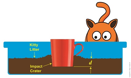
Objects in motion inevitably meet with opposing forces, a theme which I frequently encounter in my work as an engineering expert. Today we’ll calculate the opposing force our exemplar coffee mug meets when it falls into a pan of kitty litter, thus transforming its freefalling kinetic energy into the work required to move through clay litter.
Let’s revisit the Work-Energy Theorem formula, whose terms were explained in last week’s blog,
F × d = – ½ × m × v12 (1)
The left side of this equation represents the mug’s work to move through the litter, while the right side represents its kinetic energy, which it gained through freefall. To solve for F, the amount of force acting in opposition to the mug’s mass m as it plows a depth d into the litter, we’ll isolate it on one side of the equation, as shown here,
F = [- ½ × m × v12 ] ÷ d (2)
So how do we solve for F when we don’t know the value of v1, the mug’s freefall velocity at impact? We’ll use the fact that The Law of Conservation of Energy tells us that all energies are equal, and we’ll eliminate the part of Equation (2) that contains this unknown variable, that is, the right side of the equation which deals with kinetic energy. In its place we’ll substitute terms which represent the mug’s potential energy, that is, the latent energy held within it as it sat upon the shelf prior to falling. Equation (2) then becomes,
F = [- m × g × h] ÷ d (3)
where g is the Earth’s acceleration of gravity factor, a constant equal to 9.8 meters/sec2 , and h is the height from which the mug fell.
Kinetic Energy Meets With Opposing Force
So if we know the mug’s mass, the distance fallen, and the depth of the crater it made in the litter, we can determine the stopping force acting upon it at the time of impact. It’s time to plug numbers.
Let’s say our mug has a mass of 0.25 kg, it falls from a height of 2 meters, and it makes a crater 0.05 meters deep. Then the stopping force acting upon it is,
F = [- (0.25 kg) × (9.8 meters/sec2) × (2 meters)] ÷ (0.05 meters)
= – 98 Newtons
The mug was subjected to -98 Newtons, or about -22 pounds of opposing force when it fell into the litter, that resistance being presented by the litter itself.
Next time we’ll see what happens when our mug strikes a hard surface that fails to cushion its impact. Energy is released, but where does it go?
Copyright 2016 – Philip J. O’Keefe, PE
Engineering Expert Witness Blog
____________________________________ |
Tags: distance, engineering expert, falling objects, force, kinetic energy, law of conservation of energy, mass, Newtons, potential energy, velocity, work-energy theorem
Posted in Engineering and Science, Expert Witness, Forensic Engineering, Innovation and Intellectual Property, Personal Injury, Product Liability | Comments Off on When Kinetic Energy Meets With Opposing Force
Monday, January 11th, 2016
|
Last time my engineering expertise was put to the test when it was discovered that Santa’s sleigh was being hampered by a strong gust of wind. At that time we introduced the Work-Energy Theorem to determine how strong the wind’s opposing force was, and today we’ll work with the Theorem to compute just what Rudolph was up against. Here again is the expanded, workable version of the Work-Energy Theorem as introduced last time,
F × d = ½ × m × [v22 – v12]
where F is a force acting upon a moving object of mass m over a distance d to slow it from an initial velocity of v1 to a final velocity of v2.
Applying the Theorem to the dynamics at play in Santa’s situation, F is the opposing wind force, which acts over a distance, d, to slow his sleigh from an initial velocity of v1 to a final velocity, v2, thus presenting Rudolph and his buddies with a real delivery challenge.
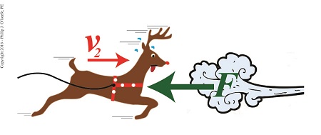 Rudolph Struggles Against a Fierce Wind Rudolph Struggles Against a Fierce Wind
If we know that Santa, his sleigh and reindeer have a combined mass of 900 kilograms — which is pretty standard for a fully loaded sleigh and reindeer team — and their initial velocity was 90 meters per second, final velocity 40 meters per second, and the distance over which the slowing took place was 760 meters, then the formula to calculate the opposing wind force becomes,
F × d = ½ × m × [v22 – v12]
F = ½ × m × [v22 – v12] ÷ d
F = ½ × (900kg) × [(40 meters/sec)2 – (90 meters/sec)2] ÷ 760 meters
F = -3848.7 Newtons = -865.2 Pounds
The minus sign signifies that the wind must exert an opposing force of 865.2 pounds in order to slow Santa’s sleigh down.
In order for Santa to get back on his delivery schedule, Rudolph is going to have to make up for lost time by expending extra energy. We’ll see how he does that next time.
Copyright 2015 – Philip J. O’Keefe, PE
Engineering Expert Witness Blog
____________________________________ |
Tags: distance, engineering expert, force, mass, Newtons, pounds, velocity, Work-EnergyTheorem
Posted in Engineering and Science, Expert Witness, Innovation and Intellectual Property, Personal Injury | Comments Off on The Work-Energy Theorem Applied to Santa’s Sleigh
Friday, January 1st, 2016
|
As an engineering expert I’ve applied the Work-Energy Theorem to diverse situations, but none as unique as its most recent application, the progress of Santa’s sleigh. Last week we saw how Santa and his reindeer team encountered a wind gust which generated enough force to slow them from an initial velocity of v1 to a final velocity, v2, over a distance, d. Today we’ll begin using the Work-Energy Theorem to see if Santa was able to keep to his Christmas delivery schedule and get all the good boys and girls their gifts in time.
Before we can work with the Work-Energy Theorem, we must first revisit the formula it’s predicated upon, de Coriolis’ formula for kinetic energy,
KE = ½ × m × v2 (1)
where, KE is kinetic energy, m is the moving object’s mass, and v its velocity.
The equation behind the Work-Energy Theorem is,
W = KE2 – KE1 (2)
where W is the work performed, KE1 is the moving object’s initial kinetic energy and KE2 its final kinetic energy after it has slowed or stopped. In cases where the object has come to a complete stop KE2 is equal to zero, since the velocity of a stationary object is zero.
In order to work with equation (2) we must first expand it into a more useful format that quantifies an object’s mass and initial and final velocities. We’ll do that by substituting equation (1) into equation (2). The result of that term substitution is,
W = [½ × m × v22 ] – [½ × m × v12] (3)
Factoring out like terms, equation (3) is simplified to,
W = ½ × m × [v22 – v12] (4)
Now according to de Coriolis, work is equal to force, F, times distance, d. So substituting these terms for W in equation (4), the expanded version of the Work-Energy Theorem becomes,
F × d = ½ × m × [v22 – v12] (5)
Next time we’ll apply equation (5) to Santa’s delivery flight to calculate the strength of that gust of wind slowing him down.
Copyright 2015 – Philip J. O’Keefe, PE
Engineering Expert Witness Blog
____________________________________ |
Tags: de Coriolis, distance, energy, engineering expert, force, kinetic energy, mass, velocity, wind force, work, work-energy theorem
Posted in Engineering and Science, Expert Witness, Forensic Engineering, Innovation and Intellectual Property, Personal Injury | Comments Off on The Math Behind the Work-Energy Theorem
Friday, December 25th, 2015
|
I hope all the good little boys and girls got Santa’s presents, because his sleigh was spotted yesterday on radar moving at an alarmingly slow pace.
As the radar screen here shows, the progress of Santa and his reindeer had slowed from an initial velocity of v1 to a much slower velocity of v2 over the distance, d, he traveled from his workshop.
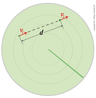
Santa’s Sleigh Tracked On Radar
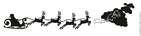
Upon closer examination, the radar operator noted that the North Wind was especially powerful this year, which caused Rudolph and the gang to double their efforts to overcome its negative force.

Santa and His Reindeer Fighting The Wind
Did Santa make it in time to deliver Christmas presents? Find out next time, when we put the developing drama into the form of mathematical equations.
Copyright 2015 – Philip J. O’Keefe, PE
Engineering Expert Witness Blog
____________________________________ |
Tags: distance, force, velocity, work-energy theorem
Posted in Engineering and Science | Comments Off on The Work-Energy Theorem Affects Santa’s Sleigh!
Sunday, November 29th, 2015
|
Although I’m an engineering expert in the 21st Century, I often have to employ engineering principles that are centuries old. A case in point is Gaspard Gustave de Coriolis‘ formula to compute work, as set out in his Principle of Work. We’ll work with his formula today, and we’ll introduce a unit of measurement used to quantify work known as the Newton.
de Coriolis’ formula to compute work is used to determine the amount of work, that is, the amount of dynamic energy available to influence the movement of an object, and is calculated by the formula,
Work = Force × Distance
where F represents the force acting upon an object that travels a distance of D. Force is most often expressed in metric units as kilogram • meter per second2, a wordy expression which is more conveniently referred to as the Newton.
In the image below, F is the force of 178 Newtons exerted by the gardener to push his filled wheelbarrow a distance of 3 meters. The quantity 178 Newtons was obtained by way of direct personal experience working in my own garden. I’ve found that it takes approximately 40 pounds of force to push a wheelbarrow loaded with dirt across level ground. Because one pound of force is equal to 4.45 Newtons, the amount of force I exerted is expressed as,
[40 pounds of force] × [4.45 Newtons per pound force] = 178 Newtons

Work = Force × Distance
If 178 Newtons of force is required to push the wheelbarrow a distance of 3 meters, then the work performed is expressed as,
Work = 178 Newtons × 3 meters
= 534 Newton • meters
Next time we’ll explore the special relationship between work and energy and introduce another unit used to quantify work.
Copyright 2015 – Philip J. O’Keefe, PE
Engineering Expert Witness Blog
____________________________________ |
Tags: de Coriolis' formula to compute work, distance, energy, engineering expert, force, Gaspard Gustave de Coriolis' principle of work, Newton, work formula
Posted in Engineering and Science, Expert Witness, Innovation and Intellectual Property, Personal Injury | Comments Off on de Coriolis’ Formula to Compute Work and the Newton
Wednesday, August 27th, 2014
|
We’ve been working towards a general understanding of how gear trains work, and today we’ll solve a final piece of the puzzle when we identify how increased gear train torque is gained at the expense of gear train speed.
Last time we developed a mathematical relationship between the torque, T, and the rotational speed, n, of the driving and driven gears in a simple gear train. This is represented by equation (8):
TDriven ÷ TDriving = nDriving ÷ nDriven (8)
For the purpose of our example we’ll assume that the driving gear is mounted to an electric motor shaft spinning at 100 revolutions per minute (RPM) and which produces 50 inch pounds of torque.
Previous lab testing has determined that we require a torque of 100 inch pounds to properly run a piece of machinery that’s powered by the motor, and we’ve decided that the best way to get the required torque is not to employ a bigger, more powerful motor, but rather to install a gear train and manipulate its gear sizes until the desired torque is obtained. We know that using this approach will most likely affect the speed of our operation, and we want to determine how much speed will be compromised.
So if the torque on the driven gear needs to be 100 inch pounds, then what will be the corresponding speed of the driven gear?
To answer this question we’ll insert the numerical information we’ve been provided into equation (8). Doing so we arrive at the following:
TDriven ÷ TDriving = nDriving ÷ nDriven
(100 inch pounds) ÷ (50 inch pounds) = (100 RPM) ÷ nDriven
2 = (100 RPM) ÷ nDriven
nDriven = (100 RPM) ÷ 2 = 50 RPM
This tells us that in order to meet our torque requirement of 100 inch pounds, the gear train motor’s speed must be reduced from 100 RPM to 50 RPM, which represents a 50% reduction in speed, hence the tradeoff.

This wraps up our blog series on gears and gear trains. Next time we’ll move on to a new topic: Galileo’s experiments with falling objects.
_______________________________________
|
Tags: distance vector, driven gear, driving gear, engineering expert witness, force, force vector, forensic engineer, gear expert, gear shaft, gear teeth, gear train, machine design expert, machinery expert, pitch circle, pitch circle radius, torque, torque calculations, torque formula, vectors
Posted in Engineering and Science, Expert Witness, Forensic Engineering, Innovation and Intellectual Property, Personal Injury, Product Liability | Comments Off on Determining the Gear Train Tradeoff of Torque vs. Speed, Part Three
Thursday, May 29th, 2014
|
Last time we developed torque equations for the driving and driven gears within a simple gear train. They are,
T1 = D1 × F
T2 = D2 × F
where, T1 and T2 are the driving and driven gear torques, D1 and D2 are the driving and driven gear pitch radii, and F is the resultant Force vector, the common factor between the two equations.

Now we’ll combine these two equations relative to F to arrive at a single equation which equates the torques and pitch circle radii of the driving and driven gears in the gear train. This type of computation is commonly used to design gear trains to ensure they perform at a given level.
As a first step we’ll use algebra to rearrange terms and place the two equations equal to F. First we’ll do it for the driving gear, dividing both sides of the equation by the pitch circle radius, D1.
T1 ÷ D1 = D1 ÷ D1 × F
T1 ÷ D1= 1 × F
F = T1 ÷ D1
In a similar fashion, we’ll do it for the driven gear by dividing both sides of the equation by the pitch circle radius, D2.
T2 = D2 × F → F = T2 ÷ D2
Since F is the common term between the two equations, we can set them up as equal to each other,
F = T1 ÷ D1 = T2 ÷ D2
which means that,
T1 ÷ D1 = T2 ÷ D2
Next time we’ll see how to use this equation to manipulate our gear train so that it acts as a torque converter by increasing T2 with respect to T1 and the ratio of D1 to D2, thus providing a mechanical advantage to the electric motor the gear train is attached to.
_______________________________________ |
Tags: consulting expert witness, engineering expert witness, force, forensic engineer, gear, gear design expert, gear train, machine design, machinery design expert, mechanical engineering expert, pitch circle, pitch radius, torque
Posted in Engineering and Science, Expert Witness, Forensic Engineering, Innovation and Intellectual Property, Personal Injury, Product Liability | Comments Off on Equating Torques and Pitch Circle Radii Within a Gear Train
Thursday, May 22nd, 2014
|
In our last blog we mathematically linked the driving and driven gear Force vectors to arrive at a single common vector F, known as the resultant Force vector. This simplification allows us to achieve common ground between F and the two Distance vectors of our driving and driven gears, represented as D1 and D2. We can then use this commonality to develop individual torque equations for both gears in the train.
In this illustration we clearly see that the Force vector, F, is at a 90º angle to the two Distance vectors, D1 and D2. Let’s see why this angular relationship between them is crucial to the development of torque calculations.
First a review of the basic torque formula, presented in a previous blog,
Torque = Distance × Force × sin(ϴ)
By inserting D1, F, and ϴ = 90º into this formula we arrive at the torque calculation, T1 , for the driving gear in our gear train:
T1 = D1 × F × sin(90º)
From a previous blog in this series we know that sin(90º) = 1, so it becomes,
T1 = D1 × F
By inserting D2, F, and ϴ = 90º into the torque formula, we arrive at the torque calculation, T2 , for the driven gear:
T2 = D2 × F × sin(90º)
T2 = D2 × F × 1
T2 = D2 × F
Next week we’ll combine these two equations relative to F, the common link between them, and obtain a single equation equating the torques and pitch circle radii of the driving and driven gears in the gear train.
_______________________________________
|
Tags: distance vector, driven gear, driving gear, engineering expert witness, force, force vector, forensic engineer, gear expert, gear shaft, gear teeth, gear train, machine design expert, machinery expert, pitch circle, pitch circle radius, torque, torque calculations, torque formula, vectors
Posted in Engineering and Science, Expert Witness, Forensic Engineering, Innovation and Intellectual Property, Personal Injury, Product Liability | Comments Off on Gear Train Torque Equations
Wednesday, May 14th, 2014
|
Last time we analyzed the angular relationship between the Force and Distance vectors in this simple gear train. Today we’ll discover a commonality between the two gears in this train which will later enable us to develop individual torque calculations for them.

From the illustration it’s clear that the driving gear is mechanically linked to the driven gear by their teeth. Because they’re linked, force, and hence torque, is transmitted by way of the driving gear to the driven gear. Knowing this we can develop a mathematical equation to link the driving gear Force vector F1 to the driven gear Force vector F2, then use that linking equation to develop a separate torque formula for each of the gears in the train.
We learned in the previous blog in this series that F1 and F2 travel in opposite directions to each other along the same line of action. As such, both of these Force vectors are situated in the same way so that they are each at an angle value ϴ with respect to their Distance vectors D1 and D2. This fact allows us to build an equation with like terms, and that in turn allows us to use trigonometry to link the two force vectors into a single equation:
F = [F1 × sin(ϴ)] – [F2 × sin(ϴ)]
where F is called a resultant Force vector, so named because it represents the force that results when the dead, or inert, weight that’s present in the resisting force F2 cancels out some of the positive force of F1.
Next week we’ll simplify our gear train illustration and delve into more math in order to develop separate torque computations for each gear in the train.
_______________________________________
|
Tags: distance vector, driven gear, driving gear, engineering expert witness, force, force vector, forensic engineer, gear expert, gear teeth, gear tooth, gear train, line of action, mathematical link, mechanical engineer, mechanical link, theta, torque, trigonometry, vector
Posted in Engineering and Science, Expert Witness, Forensic Engineering, Innovation and Intellectual Property, Personal Injury, Product Liability, Professional Malpractice | Comments Off on The Mathematical Link Between Gears in a Gear Train
Tuesday, April 29th, 2014
|
We’ve been discussing torque and how it enables more power to be available to applications such as loosening tight nuts with a wrench. Now we’ll see how those same principles apply to another application, a simple gear train.
To review, the torque formula is,
Torque = Distance × Force × sin(ϴ)
where, Distance and Force are vector magnitudes and ϴ is the angle formed between them.

Referring to the gear train illustration above, we see that Force and Distance vectors are present, just as they had been in our previous wrench/nut example. But instead of torque being created by way of force that’s applied to a wrench, things are reversed, and it’s the torque that creates the force.
You see, in the wrench/nut example, the force applied to the wrench handle created torque on the nut. In our present gear train example, the torque applied to the motor shaft is created by an electric motor exerting pressure upon the motor shaft, which in turn exerts a force upon the driving gear teeth. The driving gear is also attached to this shaft, so torque causes the driving gear to rotate along with the motor. This rotation results in a force being exerted at the point where the teeth of the driving gear mesh with the teeth of the driven gear. In other words, in the wrench/nut example force created torque, while in the present example torque creates a force.
The gear train has a pivot point, as there was in our wrench/nut example, but this time it’s located at the center of the motor shaft rather than at the center of a nut. The pivot point in both examples is where the action takes place. The motor’s shaft and driving gear rotate around it, just as the wrench jaws and handle rotated around the nut’s pivot point.
In both examples, the Distance vectors extend out from the pivot points to meet up with the Force vector’s path. In the gear train example, this Force vector path is called a line of action, as introduced earlier in this blog series. This line of action passes through to the point where the driving and driven gear teeth mesh. The force acting upon that point causes the gears in the gear train to rotate, and as they turn mechanical energy is transferred from the motor to whatever machinery component is attached to the shaft of the driven gear. The powered component will then be able to perform useful work such as cutting lumber, mixing frosting for a cake, drilling holes in steel, or propelling vehicles.
You will note that there is an angle ϴ which exists between the Distance and Force vectors. Since we have a pivot point, a Force vector, a Distance vector, and an angle ϴ, we are able to apply the torque formula to gear trains exactly as we did in our wrench/nut example. We can then use that formula to calculate how torque is transmitted between gears in the train.
Next time we’ll examine the distance and force vectors in a simple gear train.
_______________________________________
|
Tags: distance vector, driven gear, driving gear, engineering expert witness, force, force vector, forensic engineer, gear expert witness, gear teeth, gear teeth mesh, gear train, line of action, machine design, machinery, mechanical design, mechanical energy, mechanical engineer, nut, pivot point, torque, torque formula, wrench
Posted in Engineering and Science, Expert Witness, Forensic Engineering, Innovation and Intellectual Property, Personal Injury, Product Liability | Comments Off on Torque and Force


