|
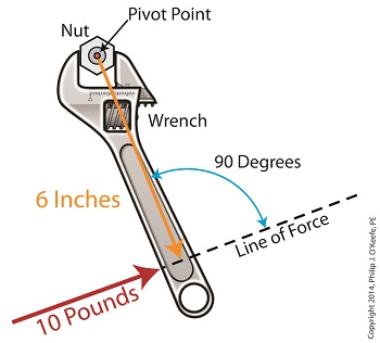
Last time we introduced the mathematical formula for torque, which is most simply defined as a measure of how much a force acting upon an object causes that object to rotate around a pivot point. When manipulated, torque can produce a mechanical advantage in gear trains and tools, which we’ll see later. The formula is: Torque = Distance × Force × sin(ϴ) We learned that the factors Distance and Force are vectors, and sin(ϴ) is a trigonometric function of the angle ϴ which is formed between their two vectors. Let’s return to our wrench example and see how the torque formula works. Vectors have both a magnitude, that is, a size or extent, and a direction, and they are typically represented in physics and engineering problems by straight arrows. In our illustration the vector for distance is represented by an orange arrow, while the vector for force is represented by a red arrow. The orange distance vector has a magnitude of 6 inches, while the red force vector has a magnitude of 10 pounds, which is being supplied by the user’s arm muscle manipulating the nut. That muscle force follows a path from the arm to the pivot point located at the center of the nut, a distance of 6 inches. Vector arrows point in a specific direction, a direction which is indicative of the way in which the vectors’ magnitudes — in our case inches of distance vs. pounds of force — are oriented with respect to one another. In our illustration the orange distance vector points away from the pivot point. This is according to engineering and physics convention, which dictates that, when a force vector is acting upon an object to produce a torque, the distance vector always points from the object’s pivot point to the line of force associated with the force vector. The angle, ϴ, that is formed between the two vectors in our example is 90 degrees, as measured by any common, ordinary protractor. Next we must determine the trigonometric value for sin(ϴ). This is easily accomplished by simply entering “90” into our calculator, then pressing the sin button. An interesting fact is that when the angle ϴ ranges anywhere between 0 and 90 degrees, the values for sin(ϴ) always range between 0 and 1. To see this in action enter any number between 0 and 90 into a scientific calculator, then press the sin button. For our angle of 90 degrees we find that, sin(90) = 1 Thus the formula for torque in our example, because the sin(ϴ) is equal to 1, simply becomes the product of the magnitudes of the Distance and Force vectors: Torque = Distance × Force × sin(90) Torque = Distance × Force × 1 Torque = Distance × Force Next time we’ll insert numerical values into the equation and see how easily torque can be manipulated. _______________________________________ |
Posts Tagged ‘force’
Torque Formula Symplified
Wednesday, April 2nd, 2014Vectors, Sin(ϴ), and the Torque Formula
Wednesday, March 26th, 2014|
Last time we introduced a physics concept known as torque and how it, together with modified gear ratios, can produce a mechanical advantage in devices whose motors utilize gear trains. Now we’ll familiarize ourselves with torque’s mathematical formula, which involves some terminology, symbols, and concepts which you may not be familiar with, among them, vectors, and sin(ϴ). Torque = Distance × Force × sin(ϴ) In this formula, Distance and Force are both vectors. Generally speaking, a vector is a quantity that has both a magnitude — that is, any measured quantity associated with a vector, whether that be measured in pounds or inches or any other unit of measurement — and a direction. Vectors are typically represented graphically in engineering and physics illustrations by pointing arrows. The arrows are indicative of the directionality of the magnitudes involved. Sin(ϴ), pronounced sine thay-tah, is a function found within a field of mathematics known as trigonometry , which concerns itself with the lengths and angles of triangles. ϴ, or thay-tah, is a Greek symbol used to represent the angle present between the Force and Distance vectors as they interact to create torque. The value of sin(ϴ) depends upon the number of degrees in the angle ϴ. Sin(ϴ) can be found by measuring the angle ϴ, entering its value into a scientific calculator, and pressing the Sin button. We’ll dive into the math behind the vectors next time, when we return to our wrench and nut example and apply vector force quantities.
_______________________________________ |
Achieving Mechanical Advantage Through Torque
Wednesday, March 19th, 2014|
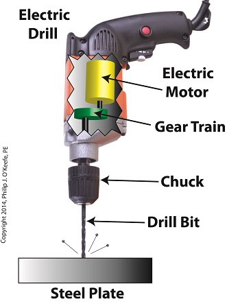
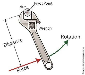
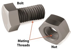
Last time we saw how gear train ratios allow us to change the speed of the driven gear relative to the driving gear. Today we’ll extend this concept further and see how gear trains are used to amplify the mechanical power output of small motors and in so doing create a mechanical advantage, an advantage made possible through the physics of torque. Below is an ordinary electric drill. Let’s see what’s inside its shell. There’s a whole lot of mechanical advantage at work here, giving the drill’s small motor the ability to perform big jobs. A motor and gear train are housed within the drill itself. The motor shaft is coupled to the chuck shaft via the gear train, and by extension, the drill bit. A chuck holds the drill bit in place. It’s the drill’s gear train that provides the small motor with the mechanical advantage necessary for this hand-held power tool to perform the big job of cutting through a thick steel plate. If the gear train and its properly engineered gear ratio weren’t in place and the chuck’s shaft was connected directly to the motor shaft, the motor would be overwhelmed and would stall or become damaged. Either way, the work won’t get done. To understand how operations like these can be performed, we must first familiarize ourselves with the physics concept of torque. Torque allows us to analyze the rotational forces acting upon rotating objects, such as gears in a gear train and wrenches on nuts and bolts. Manipulating torque allows us to achieve a physical advantage when rotating objects around a pivot point. Let’s illustrate this by using a wrench to turn a nut. The nut is fastened to the bolt with threads, interconnecting spiral grooves formed on both the inside of the nut and the outside of the bolt. A wrench is used to loosen and tighten the nut by rotating it on its mating threads. The nut itself rotates about a pivot point which lies at its center. When you use your arm to manipulate the wrench you apply force, a force which is transmitted at a distance from the pivot point. This in turn creates a torque on the nut. In other words, torque is a function of the force acting upon the handle relative to its distance from the pivot point at the center of the nut. Torque can be increased by changing one or both of its acting factors, force and distance. We’ll see how next time when we examine the formula for torque and manipulate it so that a weak arm can loosen even the tightest nut. _______________________________________ |
Condensation Inside the Steam Turbine
Sunday, September 8th, 2013|
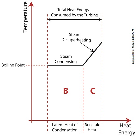
Did you know that water droplets traveling at high velocity can take on the force of bullets? It can happen, particularly within steam turbines at a power plant during the process of condensation, where steam transforms back into water. The last couple of weeks in this blog series we’ve been talking about the steam and water cycle within electric utility power plants, how heat energy is added to water during the boiling process, and how turbines run on the sensible heat energy that lies within the superheated steam vapor supplied by boilers and superheaters. We learned that without a superheater there is a very real possibility that the steam’s temperature can fall to mere boiling point. When steam returns to boiling point temperature an undesirable situation is created. The steam begins to condense into water within the turbine. To understand how this happens, let’s return to our graph from last week. It illustrates the situation when there’s no superheater present in the power plant’s steam cycle. Figure 1
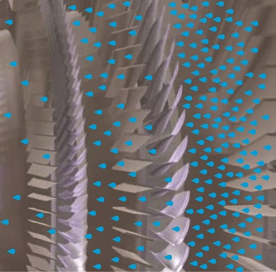
After consuming all the sensible heat energy in phase C in Figure 1, the only heat energy which remains available to the turbine is the latent heat energy in phase B. If you recall from past blog articles, latent heat energy is the energy added to the boiler water to initiate the building of steam. As the turbine consumes this final source of heat energy, the steam begins a process of condensation while it flows through the turbine. You can think of condensing as a process that is opposite to boiling. During condensation, steam changes back into water as latent heat energy is consumed by the turbine. When the condensing process is in progress, the temperature in phase B remains at boiling point, but instead of pure steam flowing through the turbine, the steam will now include water droplets, a dangerous mixture. As steam flows through the progressive chambers of turbine blades, more of its latent heat energy is consumed and increasingly more steam turns back into water as the number of water droplets increases. Figure 2 – Water Droplets Forming in the Turbine
The danger comes in when you consider that the steam/water droplet mixture is flying through the turbine at hundreds of miles per hour. At these high speeds water droplets take on the force of machine gun bullets. That’s because they act more like a solid than a liquid due to their incompressible state. In other words, under great pressure and at high speed water droplets don’t just harmlessly splash around. They hit hard and cause damage to rapidly spinning turbine blades. Without a working turbine, the generator will grind to a halt. So how do we supply the energy hungry turbine with the energy contained within high temperature superheated steam in sufficient quantities to keep things going? We’ll talk more about the superheater, its function and construction, next week.
________________________________________ |
Mechanical Power Transmission – Centrifugal Force and Centrifugal Clutches
Monday, April 9th, 2012| I’m not a big fan of amusement parks. The first time I rode on a Tilt-A-Whirl I was caught off guard and flung onto my side by the centrifugal force acting upon my body, the lower half of which was constrained by a seat belt so I wouldn’t be catapulted out during the ride. To make matters worse, the centrifugal force started to force the lunch I’d made the mistake of eating just before back up my throat. It was a very unpleasant experience to say the least.
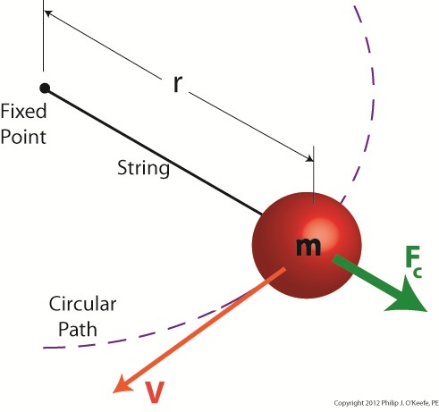
Centrifugal force is an interesting phenomenon, and its principles are involved in the operation of a centrifugal clutch, which we’ll see later. For now, let’s get a basic understanding of what it’s all about, thanks to the discoveries of Sir Isaac Newton in the late 17th Century. Figure 1
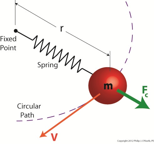
Figure 1 shows a red ball, whose mass we’ll notate m, attached to a string, the other end of which is attached to a fixed point, such as if you held it taught between your fingers. If you’re in a playful mood, you might enjoy twirling the ball above your head on its string. The distance between the center of the ball and the fixed point is labeled r, which stands for the radius of the circular path traveled by the ball as it twirls around the fixed point. The speed at which the ball travels through the air is called its straight line velocity, or tangential velocity in scientific-speak, and it is generally notated as a V. The centrifugal force, or Fc, that is exerted upon the ball as it whirls around your head is, Sir Isaac tells us, measured by the equation: Fc = mV2/r Centrifugal force in the simplest of terms is an outward-pushing force that pulls objects in motion away from the point about which they’re rotating. Let’s hold as fact that if m and r don’t change, then Newton’s equation tells us that the centrifugal force exerted upon the object in motion increases by the square of the velocity, or speed, of the ball. In other words, the faster the ball moves as you spin it around your head on the string, the harder the centrifugal force that acts upon it. As you spin the ball faster and faster, it will pull outward more and more strenuously, exerting ever greater resistance upon the string you hold between your fingers. Now suppose we replace the string in this example with a spring as shown in Figure 2. Figure 2
Why a spring? Because that’s what’s used within a centrifugal clutch. Just as with the string, the ball’s velocity increases as you increase rotation speed around the fixed point, and the centrifugal force acting upon its mass by the spinning action increases as well. The spring expands, extending further and further out from its beginning position of attachment to the fixed point, your fingers. As velocity decreases, the spring will retract, eventually returning to its original coil size. This extending and retracting action is the major mechanism at play within a centrifugal clutch. Next time we’ll explore a centrifugal clutch mechanism in more depth to observe its behavior relative to its spring under the influence of centrifugal force. ____________________________________________
|
