| Suppose it’s lunch time and you’re really starving. All day your boss has been dumping work on your desk and you’re really busy. You checked your wallet and you only have a couple of bucks. Your favorite deli sells inexpensive sandwiches that are really good, but it’s over four blocks away and the lines are long. The only thing that’s going to work for you is to find something to eat that’s both fast and cheap, so you head for the lunchroom and get one of those nasty looking sandwiches out of the vending machine. As expected, it’s not very good. It’s downright disgusting. You toss it in the trash and end up feeling angry and disappointed as you head back to the stack of work on your desk.
So what does a disgusting vending machine sandwich have to do with engineering projects? Well, engineers are often called upon to feed a very strong appetite for the design of consumer products, industrial products, and manufacturing systems. What few people outside of the engineering profession realize is that engineering design projects operate according to three constraints: cheap, fast, and good. These constraints have been around for a very long time but they have become more critical in recent times in large part due to globalization. They are shown in the engineering project triangle in Figure 1 below.
Figure 1 – The Engineering Project Triangle Here’s how the triangle works. Pick any two of the constraints but exclude the remaining third. For example, in our lunchtime scenario above you chose fast and cheap, and you ended up with food that wasn’t good. It works the same way in engineering design projects. A number of years ago I was working as a project manager at a small engineering firm. One of our customers wanted us to design a consumer electronic product chocked full of really cool features. He wanted the design completed on a fast track schedule. As I worked up a quotation, I determined that if we were to design all of the features into the product on the desired tight schedule, I would have to buy expensive design tools and put a large number of engineers to work on the project. Kind of like having the whole family pitch in to clean house versus you doing it alone. The bottom line was that although it was possible to give the customer what he wanted when he wanted it, it would cost a lot of money to pull off. This meant we could only fill two of the proscribed parameters for production, fast and good, but not cheap. In today’s fast paced, highly competitive, and minimally staffed business environment, engineers are often under a lot of pressure to somehow beat the project engineering triangle. No one wants to give up cheap, because budgets are slim and it’s extremely difficult to get more funding. No one wants to give up fast, because the marketing folks are always looking for ways to get a jump on the competition. So where does that leave “good?” Well, unless someone is going to let go of either cheap or fast, good isn’t going to happen. The end result is most often that sales and marketing end up very disappointed, dissatisfied customers proliferate, sales go down the drain, service costs go through the roof, and potential liability issues start popping up. Moral our story? Don’t fight the engineering project triangle, work with it. Start by carefully considering the project scope and all the requirements the design must satisfy. Involve engineers in the consideration process, since they’re going to be the ones who are responsible for producing the design. They know their own capabilities and what it takes to meet your expectations. Based on engineering input, set up your budget and/or schedule to ensure that you get a good result. Turns out that with engineering design, as with most things in life, effort-in equals result- out. _____________________________________________
|
Posts Tagged ‘forensic engineering’
Cheap, Fast, Good – The Engineering Project Triangle
Sunday, October 31st, 2010

Pressurized Containers – ASME Boiler and Pressure Vessel Code
Sunday, October 24th, 2010| Over the last few weeks we looked at the dangers associated with pressurized containers, also known as “pressure vessels.” We also looked at overpressure devices that can keep the pressure from building to the point where the vessel ruptures. But what about keeping pressure vessels from rupturing under normal operating pressure? You know, pressures well below the point where an overpressure device would kick in. This can happen if there is some sort of weakness in the pressure vessel caused by things like poor design, defective materials, or bad welds.
In the 19th Century the machines of the Industrial Revolution were driven by steam. Those magnificent machines advanced our civilization and standard of living. Sounds like a win-win situation, right? Wrong! The downside was that there were no standards for the design of pressure vessels like air storage tanks and boilers. Every engineer had their own ideas as to how they wanted to approach pressure vessel design. I use the word “engineer” loosely because most “engineers” of that time were not college graduates. Some approaches were good, some were bad, and some were in between. The end result was often not good. There were many pressure vessel leaks and explosions that damaged property, caused injury, and took lives. By the turn of the 20th Century industrialization spread far and wide, intensifying safety concerns about pressure vessels. One deadly incident was the straw that broke the camel’s back. On March 10, 1905, the boiler failed in a shoe factory in Brockton, Massachusetts. 58 people were killed and another 117 were injured. The factory was completely destroyed. This tragedy prompted Massachusetts to form a Board of Boiler Rules to write boiler laws. Ohio followed with their own boiler laws. This was a step in the right direction, but each state law was different and a boiler that was legal in one state was illegal in another. There was no standardization between states. In 1911 the American Society of Mechanical Engineers (ASME) formed its Boiler and Pressure Vessel Committee to address the lack of standardization. The committee’s work resulted in publication of the Boiler and Pressure Vessel Code (BPVC). In a nutshell, the BPVC establishes standardized rules governing the design, fabrication, testing, inspection, and repair of boilers and other pressurized vessels and containers. The BPVC set the standards that can be adopted by all states to minimize risk to the public. The ASME is not a government agency, so it cannot enforce compliance with the BPVC. As a matter of fact, compliance with the BPVC by manufacturers has been completely voluntary. However, most state laws now require that pressure vessels must be certified by their manufacturers to be in compliance with the BPVC before they can be sold and put into operation. A certified pressure vessel must be permanently and conspicuously marked with the manufacturer’s name, the date built, serial number, and information about its construction and the type of use it’s designed for. That wraps it up for our series about pressurized containers. Next time, we’ll shift gears and take a look at the project triangle and how it influences the outcome of engineering designs. _____________________________________________
|

Pressurized Containers – Industrial Overpressure Devices
Sunday, October 17th, 2010| Perhaps you went out on a drive to enjoy a nice summer day. As you ventured into uncharted territory, you might have ended up in an industrial area. There, you noticed factories, chemical plants, and oil refinery complexes, each surrounded by a huge system of pipes and tanks. You might have considered it to be an eyesore, but if you’re an artist and engineer like I am, you might look at it as a form of art, composed of interesting shapes, colors, and patterns. No matter how you look at it, you can bet that there are at least a few pressurized containers in there.
Last time we saw how something as seemingly harmless as a home water heater could become a dangerous missile if the pressure inside builds to the point where the tank ruptures. You can imagine what kind of explosive forces, steam, and chemicals would be unleashed into the surroundings if an industrial sized pressurized container failed due to overpressure. Let’s explore some other types of overpressure devices that are commonly used in industrial settings. One type of overpressure device is a safety valve. They are similar to a water heater relief valve, but they are generally used to relieve overpressure of gases and steam. How do they work? Basically, a safety valve is attached to the top of a pressurized container as shown in the cut away view in Figure 1 below.
Figure 1 – A Basic Safety Valve In The Closed Position A powerful spring in the valve body is designed to force down on the valve and keep it closed if there is normal pressure inside the container. Once the pressure begins to rise to an unsafe level, it pushes up against the valve and overcomes the force of the spring. The valve opens, as shown in Figure 2 below, and the contents of the pressurized container are safely vented out to an area that is normally unoccupied by people. In case you’re wondering, safety valves are commonly used on pressurized storage tanks and boilers.
Figure 2 – A Basic Safety Valve In The Open Position Another way to address the overpressure scenario is to employ a rupture disc. This is in fact a purposely constructed weak spot. It is intentionally built into a pressurized container and is designed so that it will fail when pressure starts to rise. In fact, this disc is designed to fail at a pressure point just below the pressure at which the container itself would fail. The disc is usually located within a vent pipe, which is in turn connected to the container. Should the disc rupture in an overpressure situation, the contents of the pressurized container will safely flow out of the vent pipe to a place normally unoccupied by people. The advantage of using a rupture disc is that they are made to safely release huge quantities of pressurized substances very quickly. The disadvantage in their usage is that they’re a one-time fix. That is, unlike relief or safety valves which may perform their function a multitude of times, a rupture disc is destroyed once it does its job. They are generally used in industrial settings where potential hazards are greater than at home, so once the rupture disc blows, the complete system generally undergoes a shut down so that the disc an be replaced before the pressurized container can be used again. Another option to pressure containment is the use of a fusible plug, usually constructed of a metal that will melt if the temperature within a pressurized container rises above a certain level. The metal plug melts, and excess pressure is vented through the aperture formed into a safe location. These are often used on locomotive boilers and compressed gas cylinders. Like rupture discs, fusible plugs are a one-time fix and must be replaced once they have done their job. Yet another option to pressure containment is to use a temperature limiting control. This category includes devices that monitor temperature and pressure within a pressurized container. If a dangerous situation should develop, the control system reacts, effectively reducing the pressure to prevent failure of the vessel. Automatic combustion control systems for boilers in electric utility power plants use temperature and pressure sensors to keep pressures within safe limits by regulating fuel and air input to the boiler. Next time we’ll cover the American Society of Mechanical Engineers (ASME) Boiler and Pressure Vessel Code (BPVC), which establishes rules governing the design, fabrication, testing, inspection, and repair of boilers and other pressurized containers. _____________________________________________ |


Pressurized Containers – Overpressure Devices
Sunday, October 10th, 2010| Have you ever come home to a basement full of water? The sinking feeling in your stomach at the moment of discovery is soon followed by a cascade of other emotions: fear, anger, and you probably had a few choice sailor’s words to round off the experience.
What’s just happened? Well, it may very well have been a water heater explosion, and the water on the floor may be just the beginning of the damage. Perhaps you even have a hole blown into the side of your house! Watch this video for excellent graphic footage of just such an explosion: You probably didn’t realize that the water heater in your home has the potential to become a pressure vessel, and with that present all of the potential dangers that a pressure vessel presents. Remember our discussion on the Boyle-Charles Law a few weeks ago? We learned that in the fixed volume environment of a pressurized container if the temperature keeps climbing, the pressure keeps building, and the outcome of this coupling is precisely what we’re observing in the video. The water in the water heater has turned to steam, causing pressure to build in the vessel until rupture occurs. None of us wants to come home to a basement filled with water, much less a hole blown through our house by a rocketing water heater, so how can we prevent it from happening? One answer is to have your water heater regularly serviced by a qualified plumber. The plumber would make sure that the overpressure device on the water heater tank, namely the relief valve (a.k.a. T&P valve), is in proper working order. Now you may have noticed a circle drawn around the water heater’s relief valve in the video. As their name implies, relief valves are used to relieve pressure buildup, generally of liquids. If the pressure within the water heater reaches a certain limit, set by the heater’s manufacturer, the relief valve will automatically open to vent off the pressure. A pipe on the outlet of the valve safely directs the water and steam that is let off to the floor where it can flow down to a drain. That’s why floor drains are usually located in close proximity to water heaters. Besides relief valves, overpressure devices come in many configurations, including: safety valves, rupture discs, fusible plugs, and temperature limiting controls. They may be used singly or jointly in order to perform the same basic function, that is, to keep the pressure within a vessel from building to the point where it may fail. Next week we’ll explore the other overpressure devices mentioned and where they are generally employed. _____________________________________________
|

Pressurized Containers – The Danger of Leaks
Sunday, October 3rd, 2010|
“Danger! Danger, Will Robinson!” What science fiction fan isn’t familiar with this warning cry, or the whirli-gigging robot that shouted it? The Lost in Space robot was a real scene stealer, able to glide effortlessly between Robinson’s spaceship, the vacuum of outer space, and the atmosphere of yet another alien planet without any ill effects. He was a machine. Humans are much more fragile, so the Robinson had to wear pressurized space suits for protection. These suits were pressurized containers for their bodies. Even the smallest leak in a space suit would prove disastrous. In outer space, the big rip in a suit would result in a sudden loss of pressure and expose the wearer’s body to vacuum. The vacuum would rapidly suck all of the oxygen out of the lungs and bloodstream and death would come quickly. On an alien planet with a poisonous atmosphere, the poisonous gases could leak into the suit through the rip. Back here on Earth, leaks in pressurized containers can be just as deadly. A few weeks ago we discussed pressurized containers, otherwise known as pressure vessels, and how they are no stronger than their weakest point. We were also familiarized with the Boyle-Charles Law and the way it can be used to predict how heat increases the pressure of gas within a sealed pressure vessel. In today’s article we’ll discuss some safety concerns, as when a pressure vessel fails and begins to leak. Pressurized vessels can pose a danger for various reasons. Suppose for instance that the substance leaking from it is flammable or toxic. An example would be when propane gas leaking from a storage tank mixes with air surrounding the tank. This can create an explosive mixture, readily ignited by static electricity or a nearby ignition source, such as a spark from a worker’s tool. When a toxic substance is released by a leak into an occupied area, it can be inhaled or come into contact with skin eyes, nose, and mouth, where it can enter the body and injure or kill. It might be obvious that toxic, flammable substances can prove threatening, but it is not quite as obvious that some nontoxic, nonflammable substances can be just as dangerous. For example, a substance can be heavier than air, and as it leaks out of the pressure vessel, it will roll along the floor, sinking into adjacent low spots such as basements and tunnels. This substance would then displace the air, creating a suffocation hazard for anyone who is unlucky enough to be there. Perhaps the most obvious source of danger posed by a pressurized vessel is when its contents rapidly and violently discharge. This scenario presents the same hazards mentioned above, coupled with dangers associated with flying objects and shock waves. For example, if a pressure vessel is not securely held in place and it fails, the rapid release of its contents could literally turn it into a missile careening out of control. I happened to be in close proximity to one of these “unintentional flying objects” one day. The valve broke off an unsecured pressurized gas cylinder of the type that welders use. Its gas escaped with sufficient force to cause the cylinder to fly across a concrete floor and crash through a cinderblock wall. The violent and rapid release of a pressure vessel’s contents also has the potential to create shock waves strong enough to move heavy objects and people, capable of catapulting them through the air. So it’s obvious then that the release of substances from a failed pressure vessel can lead to serious problems, but are there ways to prevent these failures from happening? Yes, there are. We’ll discuss that subject in my next installment where we will discuss, among other things, “overpressure devices.” _____________________________________________
|

CAD To The Rescue
Sunday, June 20th, 2010|
Remember Mike, the dad on The Brady Bunch, forever hunched over his drafting table while Alice, the housekeeper, regales him with yet another tale of Brady kids gone rambunctiously wrong? Although he seemed very attached to his mechanical pencil and rolls of architectural drawings, he’d have been far better off with a computer and CAD software. CAD, or Computer Aided Design, makes the life of architects, engineers, and designers of various sorts a whole lot easier. It’s been around for a few decades now, and its applications just keep getting broader. Once familiar with the workings of this software, one can produce technical diagrams in record time, and mistakes are just a delete button away from being eradicated. In fact, it’s very much like a word processor for graphics, not words. Nowadays, for all intents and purposes, the drafting table, pencils and rulers are pretty much extinct from usage by architects and engineers, much like The Brady Bunch television show. Remember the days of typewriters and carbon paper? If you do, you just dated yourself, because these haven’t been in general usage for quite some time. Word processing software and computers in general have relegated these instruments to become dusty on the shelves of historical museums. Why laboriously copy an object by hand, over and over again, when you can cut and paste your way to duplication perfection using CAD? There are even special features within CAD that allow for replication of a drawing detail in an array, meaning it is automatically replicated a specified number of times while being spaced precise distances apart along a straight line or circle. Let’s look at a simple example of how CAD makes our life so much easier. Figure l shows a single gear tooth, drawn in CAD. Figure 2 shows the tooth automatically replicated ten times and displayed in a circular array, each tooth a precise space away from its nearest neighbor. Figure 3 shows all of the gear teeth connected together with lines to form a completed drawing. Before the advent of CAD, an engineer would have had to replicate each gear tooth by hand using physical tools like a compass, pencil, and scale ruler. Figure 1 – A Single Gear Tooth Drawn With CAD
Figure 2 – A 10 Tooth Circular Array Created With CAD
Figure 3 – A Completed CAD Drawing of a 10 Tooth Gear
Another useful feature of CAD is how it can be used to annotate drawings, that is, put notes, labels, and dimensions on them. This nifty feature has rendered precise penmanship obsolete. Gone are the days when student engineers labored by hand and pencil to produce precisely the lettering and numbering conventions that are acceptable within their discipline. Poor penmanship could be disastrous to both the engineer’s career and the final product due to the difficulty it would present in reading and proper interpretation. CAD produces a level of uniformity never before possible, but of course one still needs to know how to spell! If you look back through my blog articles, you’ll see many diagrams that I created with CAD software, thus rendering complicated technical concepts easier to understand. Illustrations are most often easier to understand by the general population than the written word, and as one of my past blogs was titled, A Picture is Worth a Thousand of Them, “them” being words, of course. I also routinely use CAD software in other aspects of my profession to create everything from electrical schematics to flow charts, PowerPoint presentations slides, and engineering expert reports. _____________________________________________
|


Diesel Locomotive Brakes
Sunday, June 6th, 2010|
In the past few weeks we’ve taken a look at both mechanical and dynamic brakes. Now it’s time to bring the two together for unparalleled stopping performance. Have you ever wandered along a railroad track, hopping from tie to tie, daring a train to come roaring along and wondering if you could jump to safety in time? Many have, and many have lost the bet. That’s because a train, once set into motion, is one of the hardest things on Earth to bring to a stop. In this discussion, let’s focus on the locomotive. A large, six-axle variety is shown in Figure 1.
Figure 1 – A Six-Axle Diesel-Electric Locomotive These massive iron horses are known in the industry as diesel-electric locomotives, and here’s why. As Figure 2 shows, diesel-electric locomotives are powered by huge diesel engines. Their engine spins an electrical generator which effectively converts mechanical energy into electrical energy. That electrical energy is then sent from the generator through wires to electric traction motors which are in turn connected to the locomotive’s wheels by a series of gears. In the case of a six-axle locomotive, there are six traction motors all working together to make the locomotive move. So how do you get this beast to stop? Figure 2 – The Propulsion System In A Six-Axle Diesel-Electric Locomotive You probably noticed in Figure 2 that there are resistor grids and cooling fans. As long as you’re powering a locomotive’s traction motors to move a train, these grids and fans won’t come into play. It’s when you want to stop the train that they become important. That’s when the locomotive’s controls will act to disconnect the traction motor wires running from the electrical generator and reconnect them to the resistor grids as shown in Figure 3 below.
Figure 3 – The Dynamic Braking System In A Six-Axle Diesel Electric Locomotive The traction motors now become generators in a dynamic braking system. These motors take on the properties of a generator, converting the moving train’s mechanical, or kinetic, energy into electrical. The electrical energy is then moved by wires to the resistor grids where it is converted to heat energy. This heat energy is removed by powerful cooling fans and released into the atmosphere. In the process the train is robbed of its kinetic energy, causing it to slow down. Now you may be thinking that dynamic brakes do all the work, and this is pretty much true, up to a point. Although dynamic brakes may be extremely effective in slowing a fast-moving train, they become increasingly ineffective as the train’s speed decreases. That’s because as speed decreases, the traction motors spin more slowly, and they convert less kinetic energy into electrical energy. In fact, below speeds of about 10 miles per hour dynamic brakes are essentially useless. It is at this point that the mechanical braking system comes into play to bring the train to a complete stop. Let’s see how this switch from dynamic to mechanical dominance takes place. A basic mechanical braking system for locomotive wheels is shown in Figure 4. This system, also known as a pneumatic braking system, is powered by compressed air that is produced by the locomotive’s air pump. A similar system is used in the train’s railcars, employing hoses to move the compressed air from the locomotive to each car.
Figure 4 – Locomotive Pneumatic Braking System In the locomotive pneumatic braking system, pressurized air enters an air cylinder. Once inside, the air bears against a spring-loaded piston, as shown in Figure 4(a). The piston moves, causing brake rods to pivot and clamp the brake shoes to the locomotive’s wheel with great force, slowing the locomotive. When you want to get the locomotive moving again, you vent the air out of the cylinder as shown in Figure 4(b). This takes the pressure off the piston, releasing the force from the brake shoes. The spring in the cylinder is now free to move the shoes away from the wheel so they can turn freely. We have now returned to the situation present in Figure 2, and the locomotive starts moving again. Next week we’ll talk about regenerative braking, a variation on the dynamic braking concept used in railway vehicles like electric locomotives and subway trains. _____________________________________________
|


Brakes and Braking Systems
Sunday, May 23rd, 2010|
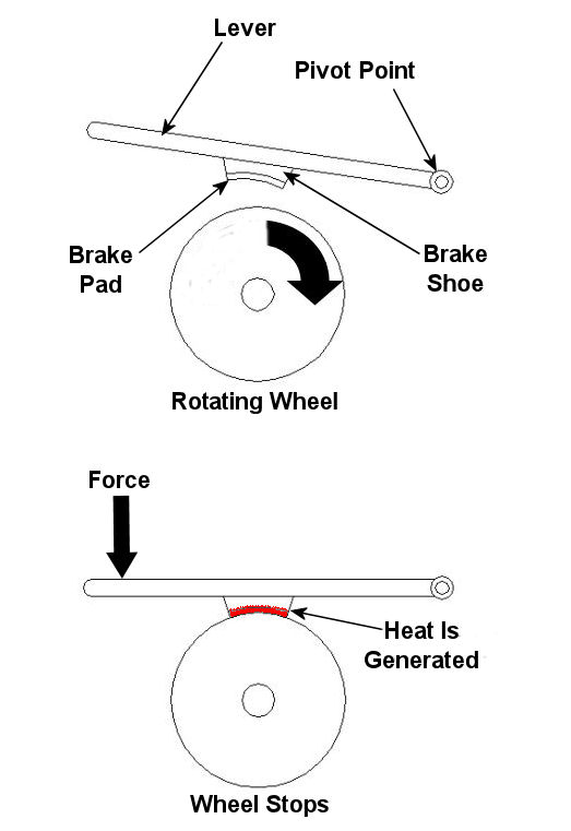
Imagine driving in your car, you’re traveling at a speed of 65 mph and you’re coming up on a curve. You depress your brake pedal to negotiate the turn, and nothing happens… Scenarios just like this one have been in the news quite often lately, brakes which just aren’t operating correctly. We’ve heard the tales of terror, recounted by those unfortunate individuals who have been placed in this situation, but have we reflected on just why their brakes might have failed? Put most simply, a brake is a device whose purpose is to stop a body in motion. This important task is accomplished by converting the kinetic energy (energy of motion) into heat energy. This can be accomplished by either of two methods, mechanically or electrically. In today’s blog we’ll focus on the mechanical aspect. A simple mechanical brake is shown in Figure 1 below. In this arrangement kinetic energy is converted into heat energy when force is applied to a lever, causing a brake shoe to meet up with a rotating wheel. The brake shoe has a pad attached to its surface that makes direct contact with the wheel, and when the two come together great friction is produced. It’s this friction that will ultimately stop the object in motion. Friction turns the kinetic energy into heat energy.
Figure 1 – A Simple Mechanical Brake Friction at its simplest is a mechanical resistance to movement. Whenever two materials in motion come into contact with each other there is always some degree of friction. The extent to which friction is produced by their meeting is referred to as the “coefficient of friction.” The coefficient of friction varies according to the surface character of the materials coming in contact. For example, the coefficient of friction for the leather sole of your shoe on smooth ice is very low. This means you’ll do a lot of slipping when you’re trying to walk, and that’s because ice presents little friction to resist a smoothly soled shoe. But take this same shoe and apply it to the rough surface of concrete, and you’ll be walking quickly and efficiently. Coefficients of friction between different materials have been duly measured in laboratories and are tabulated for easy access in engineering reference books. Based on our simple example above, one would easily come to the conclusion that a high coefficient of friction is desirable when talking about brake shoes, specifically the one represented in Figure 1 above. The higher the coefficient of friction, the more the pad wants to grab the wheel, and the less force you will need to apply to the brake shoe to successfully come to a stop. That’s mechanical braking in a nutshell. Next time, we’ll focus on an electrical braking system known as a “dynamic brake.” _____________________________________________
|


Heat Transfer in Mechanical Engineering, Part III, Radiation
Sunday, February 28th, 2010|
Last week we talked about convective heat transfer and how hot pavement in a parking lot gives up its heat to the environment. But how does the pavement get hot to begin with? This week we’ll discuss radiant heat transfer to find out. The sun is a huge nuclear furnace, separated from the earth by 93 million miles of space. The space between is just a vacuum, almost completely devoid of matter. Without contiguous solid or liquid matter between the two, heat transfer by conduction or convection can’t occur. The heat that we feel on earth is actually generated when surfaces here absorb electromagnetic energy waves emitted by the sun. Although these waves have traveled through millions of miles of space, they have not lost their punch. Our eyes perceive some of them as sunshine, but many others are not visible. But even if we can’t see them, our bodies often perceive them as heat. But radiant heat transfer isn’t a phenomenon exclusive to the sun. It can also occur when something is on fire. Intense fires can transmit tremendous amounts of radiant energy across significant distances. They can even cause combustible materials nearby to burst into flame without any direct contact being necessary. A line of sight between the source of heat and the receiving object is all that is required, and this is because radiation moves in straight lines, it can’t bend around corners. In order to calculate radiant heat transfer, we still must consider the temperature difference between the bodies, as well as the area of heat transfer, just as we did when considering the cases of conductive and convective heat transfer. But since there is no conduction or convection activity taking place, we need not concern ourselves with thermal conductivity or convection coefficients. Instead, we have to consider something called the Stefan-Boltzmann constant, a nifty little number that looks like this: 0.000000057 Watts/m2K4. It was discovered in 1879 by a scientist named Jozef Stefan. It was later derived by his student, Ludwig Boltzmann, in his work on thermodynamics and quantum mechanics. Now remember from our discussion last week the unit “K” means Kelvin (°C +273.15). Now, ideal radiant heat transfer problems involve calculations that need only consider the Stefan-Boltzmann constant. By “ideal,” I mean that there is perfect emission of radiation by one object and perfect absorption of that radiation by another. But reality is not typically so kind, and radiant heat transfer problems typically involve calculations that involve more than just the Stefan-Boltzmann constant. They involve additional calculations of terms like emissivity factors and geometric factors. What’s that? Read on. Emissivity factors relate to how well objects actually emit and absorb radiation compared to an ideal case. For example, a shiny object doesn’t absorb radiant energy as well as a dull, black object. Geometric factors are included in radiant heat transfer calculations to account for the shapes and relative orientation of the objects emitting and receiving radiation. For example, do you ever notice how the sun is hotter at noon than it is at sunset? Well, that’s because an object with a surface that’s parallel to the surface emitting radiation will receive more radiation than one that isn’t. Just to give you a basic idea of how radiant heat transfer calculations work, let’s consider an ideal situation. Suppose you own a store building with a flat roof. The store is right on the equator and it’s the vernal equinox. The roofing material is dull black, measures 20 meters by 10 meters, and it absorbs radiant energy like a sponge. But today is a dark, cloudy day, and the temperature of the roof is a cool 25°C. Now, at some point in your life I’m sure you’ve seen a documentary where scientists declared that the surface temperature of the sun is a blistering 5,400°C. Keeping this in mind, if the sun were to suddenly pop out of the clouds directly overhead at high noon, what would be the amount of radiant heat it would transfer to the roof? Well, according to Jozef Stefan, the radiant heat transfer rate can be calculated to be: Heat Flow = (The Stefan-Boltzmann Constant) x (The Area of the Roof) x ((The Sun’s Temperature)4 – (The Initial Roof Temperature)4) Now the terms we’ll need to plug into the heat flow calculation above are found as follows: The sun’s temperature is: 5,400°C + 273.15 = 5,673.15K. The temperature of the roof is: 25°C + 273.15 = 298.15K. The area of the roof is: 20 meters x 10 meters = 200 meters2. So, the heat transfer rate is: Heat Flow = (0.000000057 Watts/m2K4) x (200 m2) x ((5,673.15K) 4 – (298.15K) 4) = 11,808,605,250 Watts This would be the maximum rate of heat transfer that the roof could absorb at the instant the sun popped out of the clouds. From our example we can conclude that even in less than ideal conditions, radiant energy from the sun has the potential to generate tremendous amounts of heat on the surface of the earth. Much of this heat drives our weather as a result of convective heat transfer that takes place between the earth’s surface and our atmosphere. That wraps things up for our discussion of heat transfer in mechanical engineering. Next week we’ll talk about the importance of vibration analysis in design. Remember what happened to Jody Foster’s character in the movie Contact when the space/time device she was in began to shake violently? That’s the kind of thing vibration analysis seeks to correct! _________________________________________________________________ |

Heat Transfer in Mechanical Engineering, Part II, Convection
Sunday, February 21st, 2010|
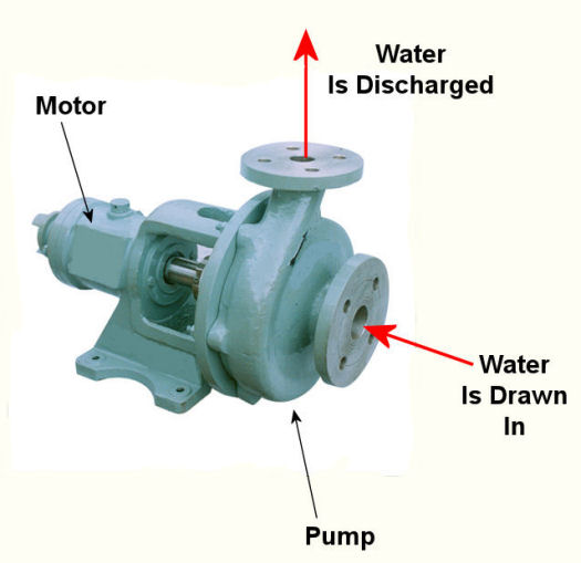
Last week we talked about heat transfer by conduction, with an example that showed how heat flowed from hot to cold through a solid block of metal. This week we’ll focus on another method of heat transfer known as convection. Convection occurs when heat is transferred between a surface and a moving fluid. As with conduction, heat always wants to flow from a higher temperature to a lower temperature. There are two types of convective heat transfer, natural and forced. An example of natural convection would be hot air rising off a blacktop highway on a sunny summer day. The cool air near the ground picks up heat from the sun-baked blacktop. As the air heats, its density decreases and it gets lighter. The warmer, lighter air rises off the highway and more cool air rolls in to take its place. This creates a continuous natural airflow that removes heat from the blacktop. You can actually see this airflow as ripples in the air just above the highway. It produces a mirage effect and almost appears to be water on the highway, particularly on very hot days. In natural convection we are concerned with heat transfer between a surface and a fluid moving over that surface. To calculate the heat transfer, we need only consider the area of the surface and the temperature difference between the surface and the fluid. There is no material thickness to consider like we saw in last week’s conductive heat transfer example, where heat was moving through a solid object. So rather than working with a conductive heat transfer coefficient, we must work with a convective heat transfer coefficient, and our engineering reference guide will guide us to the correct convective coefficient to be used to calculate heat flow. With this said, we can calculate the natural convective heat flow to be: Heat Flow = (The Convective Heat Transfer Coefficient) x (The Area That The Heat Is Flowing Through) x (The Difference In Temperature) Now let’s go back to the blacktop to see how this all works. Suppose you have a parking lot and you want to know how much heat it is pumping into the atmosphere on a hot, sunny summer day with no wind. We must first determine the area of the lot, and we measure it out to be 100 meters by 100 meters. That’s 100 X 100, or 10,000 square meters of blacktop we’re talking about. We now measure the surface temperature of the blacktop and find it to be 65°C, but the air temperature near the ground away from any source of blacktop is a cool 30°C. Okay, so what is the heat transfer? First, you consult your friendly engineering reference manual. It tells you that the convective heat transfer coefficient is 15 Watts/meter2K for still air over a horizontal surface. The “K” represents temperature measured in degrees “Kelvin,” and this is calculated by simply adding 273.15 to any temperature measured in degrees Celsius, or °C. So, to get all of our units to match up in order to perform the calculation, the blacktop would be at a temperature of 65°C + 273.15 = 338.15K. The cool air would be at a temperature of 30°C + 273.15 = 303.15K. Our equation becomes: Heat Flow = (15 W/m2K) x (10,000 m2) x (338.15K – 303.15K) = 5,250,000 Watts We have calculated that the air in the atmosphere picks up heat energy from the parking lot pavement at a rate of over 5 million watts. This explains why it always seems to be warmer in cities compared to the surrounding countryside. The presence of dark asphalt pavement and dark roofing materials absorb heat from the sun like any dark surface will, and this heat buildup then dissipates into the surrounding atmosphere through the process of natural convection. The other type of convection, the forced type, is just as its name implies. It requires a powered device to move the fluid, that is to say, it does not rely on a natural source of energy like the sun. An example of forced convection can be found in a hair dryer, which uses a small blower to move air over an electric heating element. Another example of forced convection can be found in the water pump of your car. This pump circulates water through the engine, absorbing heat as it goes, and then gives that heat up to the air which is flowing over the radiator fins. This keeps the engine from overheating. Calculating heat transfer rates in forced convection problems can get extremely complicated, involving higher level mathematics and concepts of advanced fluid dynamics. Some problems are so complex they can only be solved with the aid of specially written computer programs, so an example problem would be beyond the scope of the basic discussions in this series of articles. Next week we’ll analyze how the sun, which is separated from Earth by 93 million miles of the vacuum that we call Outer Space, is able to heat our blacktop pavement up from so great a distance. It does this by the process of radiant heat transfer. _________________________________________________________________
|


