Posts Tagged ‘friction force’

A Compound Pulley’s Numerical Puzzle is Like a Rubik’s Cube

Wednesday, February 15th, 2017

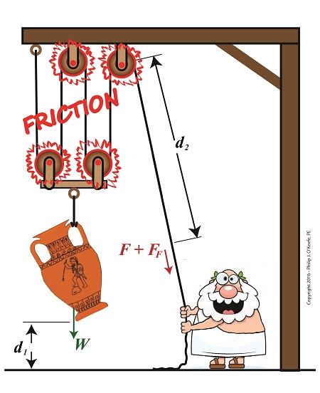
    Last time we began work on a numerical demonstration and engineering analysis of the inequality of work input and output as experienced by our example persona, an ancient Greek lifting an urn.   Today we’ll get two steps closer to demonstrating this reality as we work a compound pulley’s numerical puzzle, shuffling equations like a Rubik’s Cube to arrive at values for two variables crucial to our analysis, d2, the length of rope he extracts from the pulley while lifting, and F, the force/effort required to lift the urn in an idealized situation where no friction exists.  

A Compound Pulley’s Numerical Puzzle is Like a Rubik’s Cube

A Compound Pulley’s Numerical Puzzle is Like a Rubik’s Cube


    We’ll continue manipulating the work input equation, WI, as shown in Equation (1), along with derivative equations, breaking it down into parts, and handle the two terms within parentheses separately.   Term one, (F × d2), corresponds to the force/effort/work required to lift the urn in an idealized no-friction world.   It’ll be our focus today as it provides a springboard to solving for variables F and d2.

 WI = (F × d2) + (FF  × d2)                                       (1)

    Previously we learned that when friction is present, work output, WO, is equal to work input minus the work required to oppose friction while lifting.  Mathematically that’s represented by,

WO = WI – (FF × d2)                                                 (2)

    We also previously calculated WO to equal 80 Ft-Lbs.   To get F and d2 into a relationship with terms we already know the value for, namely WO, we substitute Equation (1) into Equation (2) and arrive at,

80 Ft-Lbs = (F × d2) + (FF  × d2)(FF × d2)             (3)

simplified this becomes,

80 Ft-Lbs = F × d2                                                   (4)

    To find the value of d2, we’ll return to a past equation concerning compound pulleys derived within the context of mechanical advantage, MA.  That is,

d2 ÷ d=  MA                                                                     (5)

And because in our example four ropes are used to support the weight of the urn, we know that MA equals 4.   We also know from last time that d1 equals 2 feet.  Plugging these numbers into Equation (5) we arrive at a value for d2,

d2 ÷ 2 ft  =  4                                                          (6)

d2 = 4 × 2 ft                                                           (7)

d2 = 8 ft                                                                 (8)

    Substituting Equation (8) into Equation (4), we solve for F,

80 Ft-Lbs = F × 8 ft                                                 (9)

F = 10 Pounds                                                          (10)

    Now that we know F and d2 we can solve for FF, the amount of extra effort required by man or machine to overcome friction in a compound pulley assembly.   It’s the final piece in the numerical puzzle which will then allow us to compare work input to output.

Copyright 2017 – Philip J. O’Keefe, PE

Engineering Expert Witness Blog

____________________________________


Friction Reduces Pulleys’ Mechanical Advantage

Tuesday, December 13th, 2016

   The presence of friction in mechanical designs is as guaranteed as conflict in a good movie, and engineers inevitably must deal with the conflicts friction produces within their mechanical designs.   But unlike a good movie, where conflict presents a positive, engaging force, friction’s presence in pulleys results only in impediment, wasting energy and reducing mechanical advantage.  We’ll investigate the math behind this phenomenon in today’s blog.

Friction Reduces Pulleys’ Mechanical Advantage

Friction Reduces Pulleys’ Mechanical Advantage


   A few blogs back we performed a work input-output analysis of an idealized situation in which no friction is present in a compound pulley.   The analysis yielded this equation for mechanical advantage,

                                                MA = d2 ÷ d1                       (1)

where d2 is the is the length of rope Mr. Toga extracts from the pulley in order to lift his urn a distance d1 above the ground.   Engineers refer to this idealized frictionless scenario as an ideal mechanical advantage, IMA, so equation (1) becomes,

                                                IMA = d2 ÷ d1                       (2)

   We also learned that in the idealized situation mechanical advantage is the ratio of the urn’s weight force, W, to the force exerted by Mr. Toga, F, as shown in the following equation.   See our past blog for a refresher on how this ratio is developed.

                                                IMA = W ÷ F                          (3)

   In reality, friction exists between a pulley’s moving parts, namely, its wheels and the rope threaded through them.   In fact, the more pulleys we add, the more friction increases.

   The actual amount of lifting force required to lift an object is a combination of FF , the friction-filled force, and F, the idealized friction-free force.  The result is FActual as shown here,

                                                FActual = F + FF                       (4)

   The real world scenario in which friction is present is known within the engineering profession as actual mechanical advantage, AMA, which is equal to,

                                                AMA = W ÷ FActual                  (5)

   To see how AMA is affected by friction force FF, let’s substitute equation (4) into equation (5),

                                                AMA = W ÷ (F + FF)                (6)

   With the presence of FF in equation (6), W gets divided by the sum of F and FF .   This results in a smaller number than IMA, which was computed in equation (3).   In other words, friction reduces the actual mechanical advantage of the compound pulley.

   Next time we’ll see how the presence of FF translates into lost work effort in the compound pulley, thus creating an inequality between the work input, WI and work output WO.

 Copyright 2016 – Philip J. O’Keefe, PE

Engineering Expert Witness Blog

____________________________________


Kinetic Energy to Work, Work to Kinetic Energy

Thursday, March 24th, 2016

    Last time we watched our example ceramic coffee mug crash to a concrete floor, where its freefall kinetic energy performed the work of shattering it upon impact.   This is a scenario familiar to engineering experts like myself who are sometimes asked to reconstruct accidents and their aftermaths, otherwise known as forensic engineering.   Today we’ll take a look at what happens when the shattered mug’s pieces are freed from their formerly cozy, cohesive bond, and we’ll watch their transmutation from kinetic energy to work, and back to kinetic energy.

    As we watch our mug shatter on the floor, we notice that it breaks into different sized pieces that are broadcast in many directions around the point of impact.   Each piece has its own unique mass, m, travels at its own unique velocity, v, and has a unique and individualized amount of kinetic energy.   This is in accordance with the kinetic energy formula, shown here again:

KE = ½ × m × v2

    So where did that energy come from?

 The Scattering Pieces Have Kinetic Energy

The Scattering Pieces Have Kinetic Energy


    According to the Work-Energy Theorem, the shattered mug’s freefalling kinetic energy is transformed into the work that shatters the mug.   Once shattered, that work is transformed back into kinetic energy, the energy that fuels each piece as it skids across the floor.

    The pieces spray out from the point of the mug’s impact until they eventually come to rest nearby.   They succeed in traveling a fair distance, but eventually their kinetic energy is dissipated due to frictional force which slows and eventually stops them.

    The frictional force acting in opposition to the ceramic pieces’ travel is created when the weight of each fragment makes contact with the concrete floor’s rough surface, which creates a bumpy ride.   The larger the fragment, the more heavily it bears down on the concrete and the greater the frictional force working against it.   With this dynamic at play we see smaller, lighter fragments of broken ceramic cover a greater distance than their heavier counterparts.

    The Work-Energy Theorem holds that the kinetic energy of each piece equals the work of the frictional force acting against it to bring it to a stop.   We’ll talk more about this frictional force and its impact on the broken pieces’ distance traveled next time.

Copyright 2016 – Philip J. O’Keefe, PE

Engineering Expert Witness Blog

____________________________________