Posts Tagged ‘friction’
Tuesday, December 13th, 2016
|
The presence of friction in mechanical designs is as guaranteed as conflict in a good movie, and engineers inevitably must deal with the conflicts friction produces within their mechanical designs. But unlike a good movie, where conflict presents a positive, engaging force, friction’s presence in pulleys results only in impediment, wasting energy and reducing mechanical advantage. We’ll investigate the math behind this phenomenon in today’s blog.
Friction Reduces Pulleys’ Mechanical Advantage
A few blogs back we performed a work input-output analysis of an idealized situation in which no friction is present in a compound pulley. The analysis yielded this equation for mechanical advantage,
MA = d2 ÷ d1 (1)
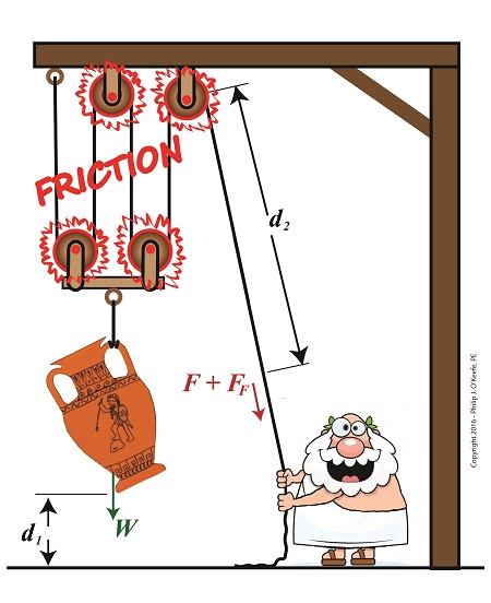
where d2 is the is the length of rope Mr. Toga extracts from the pulley in order to lift his urn a distance d1 above the ground. Engineers refer to this idealized frictionless scenario as an ideal mechanical advantage, IMA, so equation (1) becomes,
IMA = d2 ÷ d1 (2)
We also learned that in the idealized situation mechanical advantage is the ratio of the urn’s weight force, W, to the force exerted by Mr. Toga, F, as shown in the following equation. See our past blog for a refresher on how this ratio is developed.
IMA = W ÷ F (3)
In reality, friction exists between a pulley’s moving parts, namely, its wheels and the rope threaded through them. In fact, the more pulleys we add, the more friction increases.
The actual amount of lifting force required to lift an object is a combination of FF , the friction-filled force, and F, the idealized friction-free force. The result is FActual as shown here,
FActual = F + FF (4)
The real world scenario in which friction is present is known within the engineering profession as actual mechanical advantage, AMA, which is equal to,
AMA = W ÷ FActual (5)
To see how AMA is affected by friction force FF, let’s substitute equation (4) into equation (5),
AMA = W ÷ (F + FF) (6)
With the presence of FF in equation (6), W gets divided by the sum of F and FF . This results in a smaller number than IMA, which was computed in equation (3). In other words, friction reduces the actual mechanical advantage of the compound pulley.
Next time we’ll see how the presence of FF translates into lost work effort in the compound pulley, thus creating an inequality between the work input, WI and work output WO.
Copyright 2016 – Philip J. O’Keefe, PE
Engineering Expert Witness Blog
____________________________________ |
Tags: actual mechanical advantage, AMA, compound pulley, engineering, friction, friction force, ideal mechanical advantage, IMA, mechanical advantage, mechanical design, pulley, pulley friction, pulley work input, pulley work output, weight force
Posted in Engineering and Science, Expert Witness, Forensic Engineering, Innovation and Intellectual Property, Personal Injury, Product Liability | Comments Off on Friction Reduces Pulleys’ Mechanical Advantage
Monday, June 6th, 2016
|
As an engineering expert, I often use the fact that formulas share a single common factor in order to set them equal to each other, which enables me to solve for a variable contained within one of them. Using this approach we’ll calculate the velocity, or speed, at which the broken bit of ceramic from the coffee mug we’ve been following slides across the floor until it’s finally brought to a stop by friction between it and the floor. We’ll do so by combining two equations which each solve for kinetic energy in their own way.
Last time we used this formula to calculate the kinetic energy, KE, contained within the piece,
KE = FF × d (1)
and we found that it stopped its movement across the floor when it had traveled a distance, d, of 2 meters.
We also solved for the frictional force, FF, which hampered its free travel, and found that quantity to be 0.35 kilogram-meters/second2. Thus the kinetic energy contained within that piece was calculated to be 0.70 kilogram-meters2/second2.
Now we’ll put a second equation into play. It, too, provides a way to solve for kinetic energy, but using different variables. It’s the version of the formula that contains the variable we seek to calculate, v, for velocity. If you’ll recall from a previous blog, that equation is,
KE = ½ × m × v2 (2)
Of the variables present in this formula, we know the mass, m, of the piece is equal to 0.09 kilograms. Knowing this quantity and the value derived for KE from formula (1), we’ll substitute known values into formula (2) and solve for v, the velocity, or traveling speed, of the piece at the beginning of its slide.

Combining Kinetic Energy Formulas to Calculate Velocity
The ceramic piece’s velocity is thus calculated to be,
KE = ½ × m × v2
0.70 kilogram-meters2/second2= ½ × (0.09 kilograms) × v2
now we’ll use algebra to rearrange things and isolate v to solve for it,
v2 = 2 × (0.70 kilogram-meters2/second2) ÷ (0.09 kilograms)
v = 3.94 meters/second =12.92 feet/second = 8.81 miles per hour
Our mug piece therefore began its slide across the floor at about the speed of an experienced jogger.

This ends our series on the interrelationship of energy and work. Next time we’ll begin a new topic, namely, how pulleys make the work of lifting objects and driving machines easier.
Copyright 2016 – Philip J. O’Keefe, PE
Engineering Expert Witness Blog
____________________________________ |
Tags: distance, energy, engineering expert, friction, frictional force, kinetic energy, mass, velocity, work
Posted in Engineering and Science, Expert Witness, Forensic Engineering, Innovation and Intellectual Property, Personal Injury, Product Liability | Comments Off on Combining Kinetic Energy Formulas to Calculate Velocity
Wednesday, April 27th, 2016
|
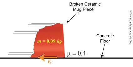
Last time we introduced the frictional force formula which is used to calculate the force of friction present when two surfaces move against one another, a situation which I as an engineering expert must sometimes negotiate. Today we’ll plug numbers into that formula to calculate the frictional force present in our example scenario involving broken ceramic bits sliding across a concrete floor.
Here again is the formula to calculate the force of friction,
FF = μ × m × g
where the frictional force is denoted as FF, the mass of a piece of ceramic sliding across the floor is m, and g is the gravitational acceleration constant, which is present due to Earth’s gravity. The Greek letter μ, pronounced “mew,” represents the coefficient of friction, a numerical value predetermined by laboratory testing which represents the amount of friction at play between two surfaces making contact, in our case ceramic and concrete.
To calculate the friction present between these two materials, let’s suppose the mass m of a given ceramic piece is 0.09 kilograms, μ is 0.4, and the gravitational acceleration constant, g, is as always equal to 9.8 meters per second squared.
Calculating the Force of Friction
Using these numerical values we calculate the force of friction to be,
FF = μ × m × g
FF = (0.4) × (0.09 kilograms) × (9.8 meters/sec2)
FF = 0.35 kilogram meters/sec2
FF = 0.35 Newtons
The Newton is shortcut notation for kilogram meters per second squared, a metric unit of force. A frictional force of 0.35 Newtons amounts to 0.08 pounds of force, which is approximately equivalent to the combined stationary weight force of eight US quarters resting on a scale.
Next time we’ll combine the frictional force formula with the Work-Energy Theorem formula to calculate how much kinetic energy is contained within a single piece of ceramic skidding across a concrete floor before it’s brought to a stop by friction.
Copyright 2016 – Philip J. O’Keefe, PE
Engineering Expert Witness Blog
____________________________________ |
Tags: coefficient of friction, Earth's gravity, engineering expert, force of friction, friction, frictional force, frictional force formula, gravitational acceleration constant, kinetic energy, Newtons, weight force, work-energy theorem
Posted in Engineering and Science, Expert Witness, Forensic Engineering, Innovation and Intellectual Property, Personal Injury, Product Liability, Professional Malpractice | Comments Off on Calculating the Force of Friction
Thursday, April 14th, 2016
|
Last time we introduced the force of friction, another force in our ongoing discussion about changing forms of energy, and we learned that it’s often a counterproductive force which design engineers and engineering experts such as myself must work to minimize in order to optimize functionality of devices we’re designing. Today we’ll introduce the frictional force formula, which computes the amount of friction present when two surfaces meet.
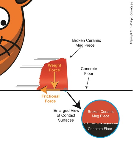
To demonstrate frictional force, we’ve been working with the example of a shattered mug’s broken ceramic pieces and watching their progress as they slide across a concrete floor. They eventually come to a stop not too far from the point where the mug shattered, because friction causes them to stop. The mass of the ceramic pieces in combination with the downward pull of gravity causes the broken bits to “bear down” on the floor, thereby maximizing contact and creating friction.
At first glance the floor and mugs’ surfaces may appear slippery smooth, but when viewed under magnification we see that both actually contain many peaks and valleys. The peaks of one surface project into the valleys of the other and it’s fight, fight, fight for the ceramic pieces to continue their progress across the floor. The strength of the frictional force acting upon the pieces is a factor of their individual weights coupled with the roughness of the two surfaces coming into contact — the shattered pieces and the floor. If friction didn’t exist and no other impediments were in the way, the pieces might travel to the next state before stopping!
Frictional Force Resists Motion
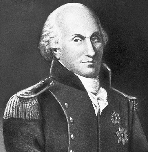
Last time we introduced Charles-Augustin de Coulomb, a scientist whose work with friction led to the later development of a formula to calculate it. It’s presented here, and frictional force is denoted as FF,
FF = μ × m × g
where, m is the mass of an object making contact with another surface and g is the gravitational acceleration constant, which is due to the force of Earth’s gravity. The Greek letter μ, pronounced “mew,” represents the coefficient of friction, a number. Numerical values for μ were determined by laboratory testing and are recorded in engineering books for many combinations of materials, including rubber on concrete, leather on steel, wood on aluminum, and our own example of ceramic on concrete.
Next time we’ll plug the numbers that apply to our ceramic-on-concrete example into the friction formula and calculate the frictional force at play.
Copyright 2016 – Philip J. O’Keefe, PE
Engineering Expert Witness Blog
____________________________________ |
Tags: Charles-Augustin de Coulomb, coefficient of friction, Earth's gravity, energy, engineering expert, friction, friction force formula, frictional force, gravitational acceleration constant, mass, mu
Posted in Engineering and Science, Expert Witness, Forensic Engineering, Innovation and Intellectual Property, Personal Injury, Product Liability | Comments Off on The Frictional Force Formula
Monday, April 4th, 2016
|
Humans have been battling the force of friction since the first cave man built the wheel. Chances are his primitive tools produced a pretty crude wheel that first go-around and the wheel’s surfaces were anything but smooth, making its usefulness less than optimal. As an engineering expert, I encounter these same dynamics when designing modern devices. What held true for the cave man holds true for modern man, friction is often a counterproductive force which design engineers must work to minimize. Today we’ll learn about frictional force and see how it impacts our example broken coffee mug’s scattering pieces, and we’ll introduce the man behind friction’s discovery, Charles-Augustin de Coulomb.
Charles-Augustin de Coulomb
Last time we learned that the work required to shatter our mug was transformed into the kinetic energy which propelled its broken pieces across a rough concrete floor. The broken pieces’ energetic transformation will continue as the propelling force of kinetic energy held within them is transmuted back into the work that will bring each one to an eventual stop a distance from the point of impact. This last source of work is due to the force of friction.
In 1785 Charles-Augustin de Coulomb, a French physicist, discovered that friction results when two surfaces make contact with one another, and that friction is of two types, static or dynamic. Although Leonardo Da Vinci had studied friction hundreds of years before him, it is Coulomb who is attributed with doing the ground work that later enabled scientists to derive the formula to calculate the effects of friction. Our example scenario illustrates dynamic friction, that is to say, the friction is caused by one of the surfaces being in motion, namely the mug’s ceramic pieces which skid across a stationary concrete floor.
While in motion, each of the mug’s broken pieces has its own unique velocity and mass and therefore a unique amount of kinetic energy. The weight of each piece acts as a vertical force pushing the piece down “into” the floor, this due to the influence of Earth’s gravitational pull, that is, the force of gravity.
Friction is created by a combination of factors, including the ceramic pieces’ weights and the surface roughness of both the pieces themselves and the concrete floor they skid across. At first glance the floor and ceramic mug’s surfaces may appear slippery smooth, but when viewed under magnification it’s a whole different story.
Next time we’ll examine the situation under magnification and we’ll introduce the formula used to calculate friction along with a rather odd sounding variable, mu.
Copyright 2016 – Philip J. O’Keefe, PE
Engineering Expert Witness Blog
____________________________________ |
Tags: calculating frictional force, Charles-Augustin de Coulomb, contacting surfaces, dynamic friction, energetic transformation, engineering expert witness, friction, frictional force, kinetic energy, Leonardo Da Vinci, roughness, static friction, work
Posted in Engineering and Science, Expert Witness, Forensic Engineering, Innovation and Intellectual Property, Personal Injury, Product Liability | Comments Off on Coulomb’s Frictional Force
Sunday, June 3rd, 2012
| My first car was a used 1963 Dodge 880. It was reliable for the most part, but one day when I stepped on the brake in a supermarket parking lot, nothing happened. I began to roll down an incline, and I struggled to steer around the maze of parked cars in the lot. After what seemed to be an eternity I managed to navigate my way out of the lot into an adjacent cornfield. The soft ground and corn stalks finally brought me to a stop. I later discovered that the reason my brakes failed is because their linings had completely worn away.
Like the brakes in cars, centrifugal clutch shoes also have linings as shown in Figure 1. Brake linings are typically made of a rough, high friction materials, such as ceramic compounds. These materials are bonded to the brake shoes, or in the case of clutches, to the clutch shoes. When centrifugal force comes into play, pressing the clutch shoes against the inside wall of the clutch housing, the roughness of the linings provides a good grip, preventing slippage between the shoes and the housing.

Figure 1
As we learned in previous articles, slip between the clutch shoes and clutch housings can create problems. In our grass trimmer for example, we learned that slippage reduces the amount of power the engine can effectively transmit to the cutter head. It also tends to produce a lot of heat. This heat can adversely effect the clutch springs and cause clutch failure.
Although the high friction lining of the clutch shoes prevents most slippage, it can still occur, as when the throttle is depressed and engine speed increases beyond idle. There is some slipping as the clutch shoes first engage with the clutch housing, and it will continue until the engine speed increases to the point where centrifugal force causes the clutch shoes to firmly press into the clutch housing.
Slippage also occurs when gasoline powered tools are subjected to operating stress. Figure 2 shows two views of a chainsaw. The first view is complete, the second shows the chain and clutch housing in isolation.

Figure 2
With the engine housing removed, we see that the saw chain is connected to a sprocket located on the centrifugal clutch housing. This sprocket is similar to those that engage the chains on bicycle wheels.
Now suppose someone decides to use the chainsaw to cut a green, sap-filled log. To make matters worse, let’s suppose the chainsaw has a dull saw chain. If you’ve ever tried doing this, you know that the sticky, sappy wood will eventually gum up the chain and stop it from moving. Since the chain is connected to the clutch housing, it stops as well. However the clutch shoes, which are driven by the engine, keep trying to move the gummed-up clutch housing, because the engine’s power is enough to overcome some of the friction. The result is that the shoes slip uselessly inside the housing.
Over time, continued slippage will cause the clutch shoes’ high friction lining to wear away. Once the lining is gone the clutch shoes will slip excessively, even when the gasoline powered tool is being employed to perform the lightest task. That’s because slipping prevents a good portion of the engine’s power from being transmitted to the cutting head.
That’s it for our series on centrifugal clutches. Next we’ll be discussing transistors, how they’re used in electronic controls to switch things on and off and perform other functions.
____________________________________________
|
Tags: brakes, centrifugal clutch, centrifugal force, chainsaw, clutch, clutch failure, clutch housing, clutch shoe, clutch shoe lining, clutch slip, clutch spring, cutter head, engine, engineering expert witness, forensic engineer, friction, gasoline engine, gasoline powered tools, grass trimmer, power transmission, saw chain, sprocket, throttle trigger, wear
Posted in Engineering and Science, Expert Witness, Forensic Engineering, Innovation and Intellectual Property, Personal Injury, Product Liability | Comments Off on Mechanical Power Transmission – Centrifugal Clutch Shoe Wear
Sunday, May 20th, 2012
|
I got my first 10-speed bike when I was in high school. It was nice, except for one nasty hangup, the brakes were always going out of adjustment. Once it did this at the worst of times, when I was going down a steep hill. I squeezed hard on the brake handles, and nothing happened. The bike started to go out of control in its ascent down the hill, and in desperation I took my feet off the pedals and pressed the soles of my shoes as hard as I could into the road surface. To my relief my emergency measure was effective. The harder I pressed into the pavement, the less my shoes slipped, and the more the bike slowed down. I had good rubber treads on the sneakers I was wearing that day, and the friction between the soles of my shoes and the surface of the pavement was strong enough to stop my runaway descent. Something very similar occurs during the operation of a centrifugal clutch.
If you recall from previous articles in this series, when the clutch mechanism spins faster than engine idle speed, the centrifugal force acting upon the clutch shoes overcomes the tension in the springs. This causes the clutch shoes to make contact with the clutch housing. But although there is contact, the clutch shoes will initially slip somewhat. That is, the clutch housing and cutter head won’t spin at exactly the same speed when a faster spin is first employed, although the slip between the clutch shoes and housing decreases as engine speed increases.
Faster speed means there’s more centrifugal force at play, forcing the shoes harder against the drum of the clutch housing. The increase in centrifugal force makes the shoes move tighter and tighter against the housing, and this causes an increase in friction. Eventually the engine speed will increase to full throttle, the point where the shoes are pressed into the housing so hard there is no more slip. The cutter head will then turn at the same rate as the engine, and the engine’s power will be fully transmitted to the cutter head, allowing you to trim grass effectively.
Friction is a double edged sword. On the one hand it reduces slip between the clutch shoes and clutch housing. On the other, the friction between the slipping shoes and clutch housing generates a lot of heat, particularly if the grass trimmer is cutting thick grass. We’ll see how that heat impacts the clutch mechanism components next week.
____________________________________________

|
Tags: centrifugal clutch, centrifugal force, clutch housing, clutch mechanism, clutch shoe, clutch slip, clutch spring, cutter head, engine, engineering expert witness, forensic engineer, friction, frictional heat, full throttle, grass trimmer, heat, power transmission
Posted in Engineering and Science, Expert Witness, Forensic Engineering, Innovation and Intellectual Property, Personal Injury, Product Liability | Comments Off on Mechanical Power Transmission – The Centrifugal Clutch and Friction
Monday, April 2nd, 2012
| I remember the days when trimming grass around trees, fences, and flower beds involved the use of hand operated clippers. You know, those scissor-like things that require you to squeeze the handles together to move the blades. Cutting seemed to take forever and there was a lot of bending, stooping, and kneeling which would kill your back and turn your knees green from grass stains. Worst of all, the repetitive motion of squeezing the handles dozens of times would cramp your hands. It was a great day when gasoline powered grass trimmers came along. Just pull the recoil starter cord and you’re ready to go. It’s fast, easy, and the final result looks better too.
If you’ve ever operated a gasoline powered tool like a grass trimmer, you probably noticed that the cutter action isn’t immediate once the engine is started. Instead, the engine enters into a much slower initial speed mode, the idle speed. The cutter moves only after the throttle trigger is depressed. This introduces more gas to the engine, causing it to speed up, and this action is due to a device called the centrifugal clutch.
A centrifugal clutch, or any type of clutch for that matter, serves one basic function, to physically disconnect, then reconnect a gasoline engine from whatever it is powering. For example, if the engine in a weed trimmer stayed permanently connected to the cutter when the engine was started, it would pose a definite safety hazard. Even at idle speed, the cutter would immediately kick into high speed operational mode, and if someone wasn’t prepared for this instant response there would be a good probability of injury.
When a centrifugal clutch is placed between the engine and the cutter, it automatically disconnects the engine from the cutter during starting and at idle speed. We’ll see how it does that in a later blog. For now, let’s consider the fact that the idle function serves as a “get ready.” The user is able to both psychologically and physically prepare themselves to use their tool. Pressing the trigger revs the engine up and causes the centrifugal clutch to connect the engine to the cutting action. When the operator takes their finger off the throttle trigger the engine returns to idle speed, and the clutch automatically disconnects the engine from the cutter. The cutter becomes idle.
Figure 1
Figure 1 shows a gas trimmer and its centrifugal clutch. The engine is on one end of the trimmer and the cutter at the other. A hollow metal tube runs between them. This tube contains the cutter drive shaft. The centrifugal clutch and its clutch housing are located in a cone shaped compartment between the engine and the metal tube. The clutch is connected to the engine drive shaft and the clutch housing is connected at the other end of the cutter drive shaft. When they’re assembled into the grass trimmer, the clutch fits within the clutch housing.
Next time we’ll see how the centrifugal clutch on a grass trimmer uses centrifugal force and friction to automatically transmit mechanical power from the gas engine to the cutter.
____________________________________________
|
Tags: centrifugal clutch, clutch, clutch housing, cutter, cutter drive shaft, drive shaft, engine drive shaft, engineering expert witness, forensic engineer, friction, gasoline powered grass trimmer, grass trimmer, hand held gasoline powered tool, hollow metal tube, idle speed, injury, mechanical power transmission, recoil starter, safety hazard, throttle trigger, weed trimmer, weed wacker
Posted in Engineering and Science, Expert Witness, Forensic Engineering, Innovation and Intellectual Property, Personal Injury, Product Liability | Comments Off on Mechanical Power Transmission – Centrifugal Clutches
Sunday, July 18th, 2010
Did you know that even a perpetual motion machine will eventually come to a stop due to uncontrollable factors?
Well, uncontrollable factors are at play in power plants, too. If you recall from our last article, heat rate is industry jargon for gauging how efficiently a coal-fired power plant is operating. We learned that heat rate can be affected by things like missing thermal insulation on pipes and equipment. Missing insulation is, of course, a thing that is under human control and easily corrected, but there are some things that affect heat rate that we just can’t do anything about. They’re called, appropriately enough, uncontrollable factors.
Uncontrollable factors exist because anything devised and made by fallible humans who are beholden to the myriad laws of the universe cannot be 100 percent efficient. At their best utility coal fired power plants have an overall efficiency of between 30 and 40 percent. That means 60 to 70 percent of the energy available in the coal gets lost in the process of generating electricity. A terrible waste, right? And yet there’s nothing we can do to trim these losses until improvements in the present level of technology take place. Just as our ability to track microbes is dictated by the strength and accuracy of our magnifying equipment, so are we hampered by the tools we have at our disposal to deal with inefficiencies such as energy losses.
So where does this energy get lost due to uncontrollable factors? The first and probably most obvious place to look is the smoke stack. Energy is also lost in three other ways: friction between equipment parts, auxiliary power consumption, and in a piece of equipment known as a condenser. Let’s look at each.
In the most basic of terms, when coal is introduced into a power plant boiler it is combined with air and burned. This burning process releases heat energy, but it also forms gases that contain nitrogen and compounds like carbon monoxide and carbon dioxide. There’s also some water vapor formed by moisture in the coal and air. These gases and vapor absorb some of the heat energy released. To keep the combustion process going the gases and vapor must be removed from the boiler by powerful fans and sent up the smoke stack. Now, boilers are designed to absorb much of the heat energy from the gases and vapor that make their way to the stack, but they cannot possibly absorb it all. The result is that a significant amount of heat escapes up the smoke stack into the atmosphere along with the gases.
Friction between parts is present everywhere in a power plant. It exists in the bearings on the shafts of motors, pumps, and steam turbines, slowing them down and hindering their operating capacity. Friction also exists where moving water and steam are present, impeding their ability to flow through piping systems. There is even friction working against the steam as it flows through parts in the turbine. Extra energy has to be expended to overcome this friction. This is energy that could be used to generate electricity.
Now at some point in your life you’ve probably heard it said, “You need money to make money,” and this is very true. It takes a certain investment of resources to produce a profit-making enterprise. This investment principle holds true for the making of electricity, too. The bottom line is you need electricity to make electricity. Specifically, you have to use significant amounts of electricity to power machinery that is essential to move coal, air, combustion gases, and water through the process of making electricity in the power plant. This is called auxiliary power. It’s the electricity siphoned off by the various pieces of equipment in a power plant in its quest to generate electrical energy to be sold to customers.
Another major factor at play in uncontrollable energy losses is in a piece of equipment integral to the very function of power plants: the condenser. It comes into play when water is boiled to make steam which then travels through the turbine, spinning its electrical generator and creating electric power. Unfortunately even the most efficient of steam turbines cannot use 100% of the heat energy coming at it from the steam.
You see, after steam leaves the turbine, it’s turned back into water by a condenser so it can be sent back to the boiler to be turned into steam again. One of the reasons that this is done is so that the boiler does not have to be continuously filled with fresh, purified water. Water purification is necessary to keep minerals, seaweed, fish scales, and other nasty things from clogging up and damaging the boiler and steam turbine, and purified water is not as readily available as, say, lake water. The condenser acts as a heat exchanger that is hooked up to the steam turbine exhaust. It has tubes inside of it in which cold water flows, water which is drawn in from a nearby body of water, most often a river or lake. As steam blows across the outside of the cold water tubes in the condenser, it gives up its remaining heat energy and condenses into water again, then it is returned to the boiler to repeat its journey. The river water within the tubes of the condenser flows back into the river, carrying with it the heat energy removed from the steam.
That wraps up our discussion about coal power plant efficiency. Next time we’ll discuss a new topic: coal fired power plant furnace explosions.
_____________________________________________
|
Tags: auxiliary power, boiler, coal power plant efficiency, condenser, electric utility, electrical generator, electricity, engineering expert witness, forensic engineer, friction, heat energy, heat rate, smoke stack, steam turbine
Posted in Engineering and Science | Comments Off on Coal Power Plants, Far From Perfect


