|
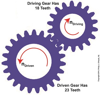
Last time we learned there are two formulas used to calculate gear ratio, R. Today we’ll see how to use them to calculate a gear reduction between gears in a gear train, a strategy which enables us to reduce the speed of the driven gear in relation to the driving gear. If you’ll recall from last time, our formulas to determine gear ratio are: R = NDriven ÷ NDriving (1) R = nDriving ÷ nDriven (2) Now let’s apply them to this example gear train to see how a gear reduction works. Here we have a driven gear with 23 teeth, while the driving gear has 18. For our example the electric motor connected to the driving gear causes it to turn at a speed, nDriving, of 3600 revolutions per minute (RPM). Knowing these numerical values we are able to determine the driven gear speed, nDriven. First we’ll use Formula (1) to calculate the gear ratio using the number of teeth each gear has relative to the other: R = NDriven ÷ NDriving R = 23 Teeth ÷ 18 Teeth R = 1.27 In gear design nomenclature, the gear train is said to have a 1.27 to 1 ratio, commonly denoted as 1.27:1. This means that for every tooth on the driving gear, there are 1.27 teeth on the driven gear. Interestingly, the R’s in both equations (1) and (2) are identical, and in our situation is equal to 1.27, although it is arrived at by different means. In Formula (1) R is derived from calculations involving the number of teeth present on each gear, while Formula (2)’s R is derived by knowing the rotational speeds of the gears. Since R is the common link between the two formulas, we can use this commonality to create a link between them and insert the R value determined in one formula into the other. Since we have already determined that the R value is 1.27 using Formula (1), we can replace the R in Formula (2) with this numerical value. As an equation this looks like: R = 1.27 = nDriving ÷ nDriven Now all we need is one more numerical value to solve Formula (2)’s equation. We know that the speed at which the driving gear is rotating, nDriving , is 3600 RPM. We use basic algebra to calculate the driven gear speed, nDriven : 1.27 = 3600 RPM ÷ nDriven nDriven = 3600 RPM ÷ 1.27 = 2834.65 RPM Based on our calculations, the driven gear is turning at a speed that is slower than the driving gear. To determine exactly how much slower we’ll calculate the difference between their speeds: nDriving – nDriven = 3600 RPM – 2834.65 RPM ≈ 765 RPM So in this gear reduction the driven gear turns approximately 765 RPM slower than the driving gear. Next time we’ll apply a gear reduction to a gear train and see how to arrive at a particular desired output speed. _______________________________________ |
Engineering Expert Witness Blog
Published by Philip J. O'Keefe, PE, MLE


