|
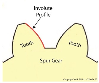
Last time we learned how spur gears mesh together to form a gear train and we examined a train consisting of just two gears, one being the driving gear, the other the driven gear. Today we’ll take a look at the geometry behind the smooth functioning of modern spur gear teeth when we identify their peculiar shape to be that of an involute curve. The curved profile of spur gear teeth conforms to a type of mathematical curve found in geometry known as an involute. The involute profile of a spur gear tooth is shown in red below. The mathematical notion of the involute was first presented in 1673 by Dutch mathematician Christiaan Huygens, in his book, Horologium Oscillatorium. Huygens’ book presents his studies on clock pendulums and the applied mathematics he used in an effort to predict their often erratic motion on ships at sea. His book ultimately dealt with far more than this, resulting in a treatise on the mathematical properties of the involutes of curves. To see how an involute curve is formed, we’ll conduct a simple experiment. One end of string is attached with a tack to a circular object, like the yellow rod shown in the following illustration. The other end of string has a red ball attached to it.
 Forming An Involute Curve If we grab the ball and pull the string taught while wrapping the string around the rod, the ball’s path will form an involute curve due to the incremental shortening of the string that occurs as it wraps around the rod. Next time we’ll see how the involute profile of gear teeth contributes to efficient mechanical energy transmission in gear trains. _______________________________________ |
Posts Tagged ‘gears’
Spur Gear Tooth Geometry and the Involute Curve
Sunday, January 19th, 2014
Gear Trains
Monday, January 13th, 2014|
Last time we covered the basic terminology of spur gears. Today we’ll see how they interact with one another to form a gear train, such as the one depicted below.
 Meshing Spur Gears Form A Gear Train A gear train is formed when the teeth of two or more gears mesh and work together for the purpose of powering a mechanical device. A gear train can consist of as little as two gears, but trains can be so large as to contain dozens of gears, depending on the complexity of the device they are powering. But no matter how many gears are employed, there are certain key features that are shared by every gear train assembly. First, one gear within the train must be attached to a shaft rotated by a source of mechanical energy, such as an engine or electric motor. This gear is called the driving gear. The second requirement of a gear train is that at least one gear other than the driving gear is mounted to the shaft of a rotating machine part. This gear is called the driven gear.
 Locomotive Gear Train Consisting Of Two Gears The illustration above shows an exploded view of a locomotive gear train assembly consisting of two gears. The driving gear is mounted to the shaft of an electric traction motor. The driven gear is mounted to the locomotive’s axle. When a motor is attached to the axle, the two gears mesh together. The traction motor converts electrical energy into mechanical energy, which is supplied to the driving gear via the spinning motor’s shaft. The teeth of the driving gear then transmit the motor’s mechanical energy to the teeth of the driven gear, which then turn the locomotive’s wheels. It’s just one of countless operations that can be performed with gear train assemblies. Next time we’ll examine the geometry behind modern spur gear tooth design. _______________________________________ |
Gear Terminology
Sunday, January 5th, 2014|
Last time we reviewed the ancient origins of gears and saw how they’ve been around a lot longer than most people realize. Now let’s familiarize ourselves with the terminology of modern gears by taking a look at the most basic and commonly used gear construction, the spur gear. A spur gear is shown below, so named due to its resemblance to spurs commonly found attached to horse riding boots.  Spur Gear At their most basic gears are wheels containing many projections which resemble teeth. These teeth are equally spaced around the wheel’s circumference and are designed to mesh, or fit together, with the teeth of other like gears. Looking more closely at the teeth of a modern spur gear, we see they have a rather complex and peculiar curved shape, along with their own terminology.  Gear Tooth Terminology There’s a pitch circle that intersects each gear tooth between the root of the tooth, or bottom land, and the tip of the tooth, or top land. Above the pitch circle each tooth side bears a face. Below the pitch circle and under each face is a flank. Spur gear teeth don’t necessarily have to have this shape. All that’s required is that the teeth fit together in such a way so as to permit fluid interaction between them as they rotate. As a matter of fact, some primitive gears consisted of wooden wheels with teeth made of wooden pegs. These pegs were inserted into evenly spaced holes which were drilled around the circumference of the wheel. The wooden pegs of each wheel would mesh with one another, and when one gear wheel was caused to rotate, its pegs would press against the pegs of the other gear, making it rotate along with it. So if simple pegs worked well enough, then why are modern gear teeth so specifically shaped? We’ll see why next time when we join gears together to form a gear train. ________________________________________ |
The History of Gears
Monday, December 23rd, 2013|
Could it be that after cave men invented the wheel they moved on to invent another circular object, the gear? Gear assemblies are found in a wide variety of applications, from tiny ones used inside wrist watches to massive ones found in aircraft carriers. No one knows for certain when gear technology was first employed, but we do know that gear driven machinery has been around since before the Industrial Revolution. As far back as the Renaissance we’ve documented their use within flour milling equipment and the first primitive clocks. Going even further back in time, Roman engineers are known to have developed a primitive gear driven odometer. It was attached to horse drawn cart wheels and the number of revolutions performed allowed the distance traveled to be calculated. In fact gears have been used far longer than scientists originally thought. In October of the year 1900 sponge divers stumbled upon an ancient Roman shipwreck at the bottom of the Aegean Sea near the Greek island of Antikythera. Inside this wreck they found mineral encrusted fragments of an artifact composed of a bronze alloy. This amazing discovery appeared to be a remarkably modern looking gear assembly which would come to be known as the Antikythera Mechanism.
 The Antikythera Mechanism Analysis of the Mechanism conducted over the last 100 years has revealed it to be a highly complex device. Still visible engraved inscriptions disclose it to be of Greek origin, dating back to about 100 BC. As such it’s the oldest known complex gear driven mechanism in the world. Prior to its discovery it was thought that mechanisms of its kind were not made until 1400 AD. As to the purpose it served, that remains a subject of controversy, since many of its parts are missing.
 X-Ray View of the Antikythera Mechanism The X-ray image reveals some of the Mechanism’s hidden complexity. Based on detailed examination of these images coupled with engineering analysis, it’s theorized by scientists that the mechanism may have been configured as illustrated below.
 Possible Configuration of the Antikythera Mechanism Since there’s no evidence that ancient Greeks possessed motors, such as those used in modern clocks, some scientists believe that the gears in the Mechanism were set into motion by simply turning a hand crank. Others believe that the arrangement and size of the gears indicate that the Mechanism’s movement is analogous to planetary motion within our solar system. They theorize further that it may have been used to calculate the positions of the Sun, Moon, and other celestial bodies. Next time we’ll fast forward to present day to familiarize ourselves with the basic terminology of gears and then later see how they’re used in modern devices.
________________________________________ |
Determining Patent Eligibility – Part 4, Machines of a Different Kind
Sunday, April 28th, 2013|
During 6th grade science we had a chapter on Simple Machines, and my textbook listed a common lever as an example, the sort that can be used to make work easier. Its illustration showed a stick perched atop a triangular shaped stone, appearing very much like a teeter-totter in the playground. A man was pushing down on one end of the stick to move a large boulder with the other end. Staring at it I thought to myself, “That doesn’t look like a machine to me. Where are its gears?” That day I learned about more than just levers, I learned to expect the unexpected when it comes to machines.
Last time we learned that under patent law the machine referred to in federal statute 35 USC § 101 includes any physical device consisting of two or more parts which dynamically interact with each other. We looked at how a purely mechanical machine, such as a diesel engine, has moving parts that are mechanically linked to dynamically interact when the engine runs. Now, lets move on to less obvious examples of what constitutes a machine. Would you expect a modern electronic memory stick to be a machine? Probably not. But, under patent law it is. It’s an electronic device, and as such it’s made up of multiple parts, including integrated circuit chips, resistors, diodes, and capacitors, all of which are soldered to a printed circuit board where they interact with one another. They do so electrically, through changing current flow, rather than through physical movement of parts as in our diesel engine. A transformer is an example of another type of machine. An electrical machine. Its fixed parts, including wire coils and steel cores, interact dynamically both electrically and magnetically in order to change voltage and current flow. Electromechanical, the most complex of all machine types, includes the kitchen appliances in your home. They consist of both fixed and moving parts, along with all the dynamic interactions of mechanical, electronic, and electrical machines. Next time we’ll continue our discussion on the second hurtle presented by 35 USC § 101, where we’ll discuss what is meant by article of manufacture. ___________________________________________ |

Determining Patent Eligibility – Part 3, What Constitutes a Machine?
Sunday, April 21st, 2013|
One of my favorite toys as a kid was Mr. Machine. He was a windup mechanical man that swung his arms when he walked while repeatedly squawking a strange YAK! sound. His body was transparent, so all the gears and levers inside were visible, and he even came with his own repair wrench. Alas, his wrench was of little use when Mr. Machine took a tragic fall down the basement stairs. Mr. Machine was aptly named. There’s no question but that he was a machine, because his inventor received a US patent, No. 3,050,900. In order to accomplish this he had to have met guidelines set out in federal statutes, specifically those contained in 35 USC § 101. He had to prove that Mr. Machine was a bona fide machine.
If you’ll recall from last week’s discussion, in order to secure a patent, inventions must prove to be original technology that is classifiable as a machine, an article of manufacture, a composition of matter, or a process, or an improvement upon same. Last week our focus was on utility, the first hurdle that an invention must jump for it to be patent eligible. Let’s continue our discussion on patentability by examining the second hurtle. When you consider the word machine, you might imagine something containing mechanical parts, like my childhood mechanical friend. But in the world of patents that’s not necessarily the case. There, a machine can be mechanical, electrical, electronic, or electromechanical in nature. In other words, a machine can include anything from a cell phone to a rocket. To be precise, under patent law the definition of machine includes any physical device consisting of two or more parts which dynamically interact with each other. For example, a purely mechanical machine, such as a diesel engine, has many moving parts. Those parts, the pistons, connecting rods, etc., are mechanically linked to dynamically interact, or move together, when the engine runs. Next week we’ll consider less obvious examples of what constitutes a machine under patent law. ___________________________________________ |


Determining Patent Eligibility – Part 2, Utility
Sunday, April 14th, 2013|
When I was growing up in the 1960s the Chicago Tribune featured a comic strip by Bill Holman called Smokey Stover. Smokey was a fireman who had all sorts of ridiculous, nutty, and even bazaar inventions, like his two-wheeled fire truck called the “Foomobile.” In the real world his inventions could never work, but that didn’t stop me from being a kid and enjoying Smokey’s goofy adventures.
Smokey’s fire truck would never pass a patent test. Why? Because it wouldn’t get past the first requirement for patentability, that is, utility. Last time we introduced the federal laws governing patents as found in Title 35, Section 101, of the United States Code (USC), 35 USC § 101 for short. It sets out requirements for patentability, and the first hurdle that an invention must jump is that it must possess the quality of utility. In other words, it must be useful. This quality of utility prevents ridiculous and/or hypothetical devices, such as Smokey’s Foomobile, from receiving a patent. Because the Foomobile consists of an engine and two wheels mounted on a single axle, there’s nothing to keep it from falling over. The weight of its engine makes it front-heavy and unstable. The nutty vehicle will tip forward, and its front bumper will become wedged in the ground. The Foomobile is just not capable of passing the test of utility because it cannot be operated as intended – Smokey would never make it to the scene of the fire – and it’s unable to provide any identifiable benefit to its users. Once the hurdle of proving an invention’s utility is passed, the next considerations for patent eligibility must be addressed. Is the invention a machine? A process? Just what defines a machine? Is it something with gears and a motor? Next time we’ll see how within the context of patent eligibility, the word machine can apply to things which are not at all mechanical. ___________________________________________ |

Systems Engineering In Medical Device Design – Preproduction, Part I
Monday, February 4th, 2013| If you’ve been following along with our blog discussion on the systems engineering approach to medical device design, you should by now be convinced that instructions are important. In fact, the meticulous instructions produced during the manufacturing, operating, and maintenance phases of the Development stage are also crucial to later stages, that of Production and Utilization. Let’s finish up our discussion on the Development stage by taking a look at its final aspect, Preproduction.
The Preproduction aspect is instrumental to nipping potential problems in the bud before the medical devices go into actual production. In the initial Preproduction stages, systems engineers coordinate with the manufacturing and purchasing departments within the company as well as outside suppliers. The goal is to acquire all parts and equipment necessary to build a limited number of medical devices on the assembly line. Subjects such as preference in molded plastic components, motors, gears, pumps, springs, electronic components, circuit boards, wire, and tubing are discussed and agreed upon. Vendors are assessed with regard to their ability to produce parts when they are needed and that meet design specifications, satisfy quality requirements, and have costs that fall within budgetary constraints. The assembly of Preproduction devices provides an opportunity for systems engineers to validate manufacturing and quality control instructions and assess the device design with regard to manufacturability, meaning, the extent to which devices can be manufactured with relative ease, at minimal cost, while maintaining maximum reliability. Devices manufactured during this aspect of the Development stage serve as a test. Are instructions clearly written? Do the device parts fit together as they should? Are parts strong enough to withstand the assembly process? Can the devices be assembled as quickly and easily as expected? If the answer is “no” to any of these questions, then the device design and instructions must be returned to the design engineers and technical writers. Heads come together to rehash things and work out the bugs. Next time we’ll continue with the Preproduction aspect of the Development stage to see how laboratory and field testing enables systems engineers to shake out any more bugs from the medical device design, operating instructions, and maintenance instructions. ___________________________________________
|

Food Manufacturing Challenges
Sunday, September 18th, 2011| Some people just have a knack in the kitchen, and my wife is among them. She transforms raw ingredients into the most amazing culinary delights, almost like she’s waving a magic wand. The finished products are works of art, hand crafted with tender loving care, and lucky me, I get to feast on them regularly!
During the course of my engineering career I’ve been employed within many industries, and at one point I made the decision to leave the electric utility industry and enter into the world of food manufacturing. I accepted the position of Plant Engineer with a wholesale manufacturer of baking ingredients and frozen pastry products. My main responsibility was the design of food manufacturing equipment and their production lines. What I had expected to be a relatively straightforward process soon proved to be more challenging. I was no longer working with hard metal as my raw material, that is, gears, nuts, and bolts, but a whole new arena of things described by adjectives such as gooey and pastey. Engineers don’t typically create food products, and let’s face it, you probably wouldn’t want to eat anything that I cooked anyway! But an engineer working within a food manufacturing plant must act as a liaison between the worlds of engineering design and the culinary arts. Now food manufacturers typically hire professional chefs to develop new products in their research and development (R&D) kitchens. Like my wife, they’re well qualified to produce wonderful hand-made culinary delights. The sticky part comes in when their small batch recipes and preparation techniques don’t translate smoothly to the world of mass production. When it comes to handling food, human fingers are far superior to metal machinery, and raw ingredients behave differently for each. Herein lies much of the challenge for design engineers within the food industry. How do you design equipment and production lines to make huge quantities of food that look and taste as good as the prototype products made by hand in the R&D kitchen? Next week we’ll find out. ____________________________________________
|

CAD To The Rescue
Sunday, June 20th, 2010|
Remember Mike, the dad on The Brady Bunch, forever hunched over his drafting table while Alice, the housekeeper, regales him with yet another tale of Brady kids gone rambunctiously wrong? Although he seemed very attached to his mechanical pencil and rolls of architectural drawings, he’d have been far better off with a computer and CAD software. CAD, or Computer Aided Design, makes the life of architects, engineers, and designers of various sorts a whole lot easier. It’s been around for a few decades now, and its applications just keep getting broader. Once familiar with the workings of this software, one can produce technical diagrams in record time, and mistakes are just a delete button away from being eradicated. In fact, it’s very much like a word processor for graphics, not words. Nowadays, for all intents and purposes, the drafting table, pencils and rulers are pretty much extinct from usage by architects and engineers, much like The Brady Bunch television show. Remember the days of typewriters and carbon paper? If you do, you just dated yourself, because these haven’t been in general usage for quite some time. Word processing software and computers in general have relegated these instruments to become dusty on the shelves of historical museums. Why laboriously copy an object by hand, over and over again, when you can cut and paste your way to duplication perfection using CAD? There are even special features within CAD that allow for replication of a drawing detail in an array, meaning it is automatically replicated a specified number of times while being spaced precise distances apart along a straight line or circle. Let’s look at a simple example of how CAD makes our life so much easier. Figure l shows a single gear tooth, drawn in CAD. Figure 2 shows the tooth automatically replicated ten times and displayed in a circular array, each tooth a precise space away from its nearest neighbor. Figure 3 shows all of the gear teeth connected together with lines to form a completed drawing. Before the advent of CAD, an engineer would have had to replicate each gear tooth by hand using physical tools like a compass, pencil, and scale ruler. Figure 1 – A Single Gear Tooth Drawn With CAD
Figure 2 – A 10 Tooth Circular Array Created With CAD
Figure 3 – A Completed CAD Drawing of a 10 Tooth Gear
Another useful feature of CAD is how it can be used to annotate drawings, that is, put notes, labels, and dimensions on them. This nifty feature has rendered precise penmanship obsolete. Gone are the days when student engineers labored by hand and pencil to produce precisely the lettering and numbering conventions that are acceptable within their discipline. Poor penmanship could be disastrous to both the engineer’s career and the final product due to the difficulty it would present in reading and proper interpretation. CAD produces a level of uniformity never before possible, but of course one still needs to know how to spell! If you look back through my blog articles, you’ll see many diagrams that I created with CAD software, thus rendering complicated technical concepts easier to understand. Illustrations are most often easier to understand by the general population than the written word, and as one of my past blogs was titled, A Picture is Worth a Thousand of Them, “them” being words, of course. I also routinely use CAD software in other aspects of my profession to create everything from electrical schematics to flow charts, PowerPoint presentations slides, and engineering expert reports. _____________________________________________
|


