Posts Tagged ‘heat energy’
Monday, January 16th, 2017
|
We left off last time with an engineering analysis of energy factors within a compound pulley scenario, in our case a Grecian man lifting an urn. We devised an equation to quantify the amount of work effort he exerts in the process. That equation contains two terms, one of which is beneficial to our lifting scenario, the other of which is not. Today we’ll explore these two terms and in so doing show how there are situations when work input does not equal work output.

Work Input Does Not Equal Work Output
Here again is the equation we’ll be working with today,
WI = (F × d) + (FF × d) (1)
where, F is the entirely positive force, or work, exerted by human or machine to lift an object using a compound pulley. It represents an ideal but not real world scenario in which no friction is present within the pulley assembly.
The other force at play in our lifting scenario, FF, is less obvious to the casual observer. It’s the force, or work, which must be employed over and above the initial positive force to overcome the friction that’s always present between moving parts, in this case a rope moving through pulley wheels. The rope length extracted from the pulley to lift the object is d.
Now we’ll use this equation to understand why work input, WI, does not equal work output, WO, in a compound pulley arrangement where friction is present.
The first term in equation (1), (F × d), represents the work input as supplied by human or machine to lift the object. It is an idealistic scenario in which 100% of energy employed is directly conveyed to lifting. Stated another way, (F × d) is entirely converted into beneficial work effort, WO.
The second term, (FF × d), is the additional work input that’s needed to overcome frictional resistance present in the interaction between rope and pulley wheels. It represents lost work effort and makes no contribution to lifting the urn off the ground against the pull of gravity. It represents the heat energy that’s created by the movement of rope through the pulley wheels, heat which is entirely lost to the environment and contributes nothing to work output. Mathematically, this relationship between WO, WI, and friction is represented by,
WO = WI – (FF × d) (2)
In other words, work input is not equal to work output in a real world situation in which pulley wheels present a source of friction.
Next time we’ll run some numbers to demonstrate the inequality between WI and WO.
Copyright 2017 – Philip J. O’Keefe, PE
Engineering Expert Witness Blog
____________________________________ |
Tags: compound pulley, engineering, friction, heat energy, pulley, work input, work output
Posted in Engineering and Science, Expert Witness, Forensic Engineering, Innovation and Intellectual Property, Personal Injury, Product Liability | Comments Off on Work Input Does Not Equal Work Output
Saturday, January 7th, 2017
|
Last time we saw how the presence of friction reduces mechanical advantage in an engineering scenario utilizing a compound pulley. We also learned that the actual amount of effort, or force, required to lift an object is a combination of the portion of the force which is hampered by friction and an idealized scenario which is friction-free. Today we’ll begin our exploration into how friction results in reduced work input, manifested as heat energy lost to the environment. The net result is that work input does not equal work output and some of Mr. Toga’s labor is unproductive.
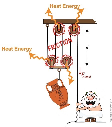
Friction Results in Heat and Lost Work Within a Compound Pulley
In a past blog, we showed how the actual force required to lift our urn is a combination of F, an ideal friction-free work effort by Mr. Toga, and FF , the extra force he must exert to overcome friction present in the wheels,
FActual = F + FF (1)
Mr. Toga is clearly working to lift his turn, and generally speaking his work effort, WI, is defined as the force he employs multiplied by the length, d, of rope that he pulls out of the compound pulley during lifting. Mathematically that is,
WI = FActual × d (2)
To see what happens when friction enters the picture, we’ll first substitute equation (1) into equation (2) to get WI in terms of F and FF,
WI = (F + FF ) × d (3)
Multiplying through by d, equation (3) becomes,
WI = (F × d )+ (FF × d) (4)
In equation (4) WI is divided into two terms. Next time we’ll see how one of these terms is beneficial to our lifting scenario, while the other is not.
Copyright 2017 – Philip J. O’Keefe, PE
Engineering Expert Witness Blog
____________________________________ |
Tags: compound pulley, engineering, friction, heat energy, lost work, mechanical advantage, pulley, reduced work, work input, work output
Posted in Engineering and Science, Expert Witness, Forensic Engineering, Innovation and Intellectual Property, Personal Injury, Product Liability, Professional Malpractice | Comments Off on Friction Results in Heat and Lost Work Within a Compound Pulley
Saturday, October 24th, 2015
|
As an engineering expert with 14 years’ electric utility experience, I’ve dealt with all types of electrical power generators, including many similar to the dynamo that James Prescott Joule used in his Experiment With Electricity. Today we’ll look inside Joule’s dynamo and see how it contributed to creating electricity as well as another of Joule’s discoveries, the Joule Heating Effect.

Dynamo-Circa Early 19th Century
In Joule’s Experiment With Electricity, the dynamo was powered by a steam engine, which enabled the dynamo’s shaft to spin. As it spun, the magnet located inside the dynamo also spun, thus creating a rotating magnetic field that surrounded the dynamo’s internal copper wire coils.
The interaction between the magnetic field and wire produced electric current which flowed inside the coils. The current ultimately made its way out of the dynamo by way of external wires, to which any number of devices could be powered when attached. The net result was the engine’s mechanical energy had been converted into electrical. To learn more about the process of producing electricity with magnets see my blog on, Coal Power Plant Fundamentals – The Generator.
As electrical energy flowed through the dynamo’s wiring, some of it was converted into heat energy. This was due to resistance posed by impurities present in the makeup of the wire, impurities which served to impede the overall flow of electric current. When electrons flowing through the wire collided with these impediments, they caused heat to build up inside the wire, a phenomenon which came to be known as the Joule Heating Effect. To read more on electrical resistance and Joule heating go to my blog, Wire Size and Electric Current.
The net result of Joule’s Experiment With Electricity was to further prove the link between chemical, heat, mechanical and electrical energies as set out in the Law of Conservation of Energy. And I suspect that knowledge was later put to use by Joule’s family for the betterment of their brewery business.
Next time we’ll use Joule’s experimental findings in conjunction with de Coriolis’ Kinetic Energy Formula to quantify the energy of the falling coffee mug we’ve been watching.
Copyright 2015 – Philip J. O’Keefe, PE
Engineering Expert Witness Blog
____________________________________ |
Tags: de Coriolis, dynamo, electric utility, electrical energy, electrical power generators, electrical resistance, engineering expert, heat energy, James Prescott Joule, Joule heating, Joule's experiment with electricity, law of conservation of energy, power plant, wire size and electric current
Posted in Engineering and Science, Expert Witness, Forensic Engineering, Innovation and Intellectual Property, Personal Injury, power plant training, Product Liability | Comments Off on Joule’s Dynamo – The Joule Heating Effect
Friday, October 16th, 2015
|
In my work as an engineering expert I’ve dealt with all forms of energy, just as we’ve watched James Prescott Joule do. He constructed his Joule Apparatus specifically to demonstrate the connection between different forms of energy. Today we’ll see how he furthered his discoveries by building a prototype power plant capable of producing electricity, a device which came to be known as Joule’s Experiment With Electricity.

Joule’s Experiment With Electricity
As the son of a wealthy brewer, Joule had been fascinated by electricity and the possibility of using it to power his family’s brewery and thereby boost production. To explore the possibilities, he went beyond the Apparatus he had built earlier and built a device which utilized electricity to power its components. The setup for Joule’s experiment with electricity is shown here.
Coal was used to bring water inside a boiler to boiling point, which produced steam. The steam’s heat energy then flowed to a steam engine, which in turn spun a dynamo, a type of electrical generator.
Tracing the device’s energy conversions back to their roots, we see that chemical energy contained within coal was converted into heat energy when the coal was burned. Heat energy from the burning coal caused the water inside the boiler to rise, producing steam. The steam, which contained abundant amounts of heat energy, was supplied to a steam engine, which then converted the steam’s heat energy into mechanical energy to set the engine’s parts into motion. The engine’s moving parts were coupled to a dynamo by a drive belt, which in turn caused the dynamo to spin.
Next time we’ll take a look inside the dynamo and see how it created electricity and led to another of Joule’s discoveries being named after him.
Copyright 2015 – Philip J. O’Keefe, PE
Engineering Expert Witness Blog
____________________________________ |
Tags: boiler expert witness, dynamo, electric current, electric current induction, electrical energy, electrical engineering expert witness, electrical generator expert witness, electrical resistance of wires, engineering expert witness, forensic engineer, heat energy, James Prescott Joule, Joule Heating Effect, magnetic field, mechanical energy, mechanical engineering expert witness, power engineering expert witness, power plant, power plant engineering expert witness, steam, wire size
Posted in Engineering and Science, Expert Witness, Forensic Engineering, Innovation and Intellectual Property, Personal Injury, power plant training, Product Liability | Comments Off on Joule’s Experiment With Electricity
Thursday, November 14th, 2013
|
Last time we learned how the formation of condensate within a power plant’s turbine results in a vacuum being created. This vacuum plays a key role in increasing steam turbine efficiency because it affects a property known as enthalpy, a term used to denote total heat energy contained within a substance. For the purposes of our discussion, that would be the heat energy contained within steam which flows through the turbine in a power plant.
The term enthalpy was first introduced by scientists within the context of the science of thermodynamics sometime in the early 20th Century. As discussed in a previous blog article, thermodynamics is the science that deals with heat and work present within processes. Enthalpy is a key factor in thermodynamics, and is commonly represented in engineering calculations by the letter h and denoted as,
h = u + Pv
where u is the internal energy of a substance, let’s say steam; P is the pressure acting upon a specific volume, v, of the steam; and P and v are multiplied together. Pressure is force per unit area and is measured in psi, pounds per square inch. For the purposes of our discussion, it’s the amount of pressure that steam places on pipes containing it.
Looking at the equation above, simple math tells us that if we increase the pressure, P, the result will be an increase in enthalpy h. If we decrease P, the result will be a decrease in h. Now, let’s see why this property is important with regard to the operation of a steam turbine.
When it comes to steam turbines, thermodynamics tells us that the amount of work they perform is proportional to the difference between the enthalpy of the steam entering the turbine and the enthalpy of the steam at the turbine’s exhaust. What is meant by work is the act of driving the electrical generator, which in turn provides electric power. In other words, the work leads to a useful outcome. This relationship is represented by the following equation,
W = h1 – h2
In terms of the illustration below, W stands for work, or potential for useful outcome of the turbine/generator process in the form of electricity, h1 is the enthalpy of the steam entering the inlet of the turbine from the superheater, and h2 is the enthalpy of the steam leaving at the turbine exhaust.

We’ll discuss the importance of enthalpy in more detail next week, when we’ll apply the concept to the work output of a steam turbine.
________________________________________
|
Tags: boiler, coal power plant, condensate, condenser, electrical generator, engineering expert witness, enthalpy difference, forensic engineer, heat energy, internal energy of steam, pipes, power plant design, power plant engineering expert, power plant operation, power plant training, pressure, specific volume of steam, steam pressure, steam turbine, steam turbine work, steam water cycle, superheater, thermodynamics, useful work, vacuum
Posted in Engineering and Science, Expert Witness, Forensic Engineering, Innovation and Intellectual Property, Personal Injury, power plant training, Product Liability | Comments Off on Enthalpy and Steam Turbines
Tuesday, November 5th, 2013
|
Last time we discussed the key functions of the make-up valve in the power plant water-to-steam cycle. Today we’re going to talk about a vacuum. No, not the kind you use around the house, the kind that’s created by the condenser inside a power plant.
As discussed previously, the condenser is a piece of equipment that turns turbine exhaust steam back into water. The water that’s formed during this process is known as condensate, and its density is higher than that of the steam it shares space with inside the condenser. That difference in density is what creates the vacuum inside the condenser vessel. Put another way, the increase in density along with the condenser’s airtight design prevent air from rushing in from outside to occupy any of the space inside the condenser, a desirable condition from an efficiency standpoint.
But to understand how all this works we’ll first have to gain an understanding of what is meant by density. A textbook would define it as the mass of a substance divided by the amount of space that that substance occupies. Let’s take steam and water for example. One pound of steam at 212°F forms a vapor cloud that occupies 26.78 cubic feet of space. If we condensed that pound of steam back into water at the same temperature, it would just about fit into a 16 ounce glass and occupy a mere 0.017 cubic feet.

The huge difference in their volumes is due to the fact that steam contains more than five times the heat energy that unheated water does. That energy makes the molecules in a cloud of steam more active, causing them to collide against each other with great force, spread apart, and occupy a larger space.
If you’re wondering what change in density has to do with vacuum in the condenser, allow me to offer an analogy. Ever canned any produce, like tomatoes, in glass jars to over-winter? Not likely, as this once common survival tactic has nearly become a lost art. But the vacuum created inside the condenser is much like the vacuum created within a mason jar during canning.
Inside the glass mason jar, a small space is intentionally left between the tomatoes and lid. During the process of boiling, or heat sterilization, this space fills with steam. Then during cooling the trapped steam condenses into water. This condensation creates the vacuum that sucks down on the jar’s lid, giving it an airtight seal, a condition which won’t allow bacteria to grow on our canned foods. You see, like us bacteria need oxygen to live, but thanks to the vacuum inside our cooked mason jar no air containing oxygen will remain inside to harbor it.
Next time we’ll continue our discussion on vacuum to see how it’s used to increase a steam turbine’s efficiency.
________________________________________
|
Tags: coal power plant, condensate, condenser, density, electrical power, energy, engineering expert witness, forensic engineer, heat energy, make up valve, power engineer, power plant, power plant training, steam and water cycle, steam turbine efficiency, vacuum
Posted in Engineering and Science, Expert Witness, Forensic Engineering, Innovation and Intellectual Property, Personal Injury, power plant training, Product Liability | Comments Off on Vacuum in a Power Plant Condenser
Tuesday, October 22nd, 2013
|
Last time we learned how the condenser within a power plant acts as a conservationist by transforming steam from the turbine exhaust back into water. This previously purified water, or condensate, contains valuable residual heat energy from its earlier journey through the power plant, making it perfect for reuse within the boiler, resulting in both water and fuel savings for the plant. Today we’ll take a look at a highly pressurized form of condensate known as boiler feed water and how it helps the power plant save money by recycling residual heat energy in the steam and water cycle.
Let’s begin by integrating the condenser into the big picture, the complete water-to-steam power plant cycle, to see how it fits in. The illustration shows that both the make-up pump and the condenser circulating water pump draw water from the same supply source, in this case a lake. The circulating water pump continuously draws in water to keep the condenser tubes cool, while the make-up pump draws in water only when necessary, such as when initially filling the boiler or to make up for leaks during operation, leaks which typically occur due to worn operating parts.

In a nutshell, the condenser recycles steam from the turbine exhaust for its reuse within the power plant. The journey begins when condensate drains from the hot well located at the bottom of the condenser, then gets siphoned into the boiler feed pump.
If you recall from a previous article, the boiler feed pump is a powerful pump that delivers water to the boiler at high pressures, typically more than 1,500 pounds per square inch in modern power plants. After its pressure has been raised by the pump, the condensate is known as boiler feed water.
The boiler feed water leaves the boiler feed pump and enters the boiler, where it will once again be transformed into steam, and the water-to-steam cycle starts all over again. That is, boiler feed water is turned to steam, it’s superheated to drive the turbine, then condenses back into condensate, and finally it’s returned to the boiler again by the boiler feed pump. Trace its journey along this closed loop by following the yellow arrows in the illustration.
While you were following the arrows you may have noticed a new valve in the illustration. It’s on the pipe leading from the water treatment plant to the boiler feed pump. Next time we’ll see how this small but important item comes into play in the operation of our basic power plant steam and water cycle.
________________________________________
|
Tags: boiler, boiler feed pump, boiler feed water, boiler operation, coal power plant training, condensate, condenser, condenser circulating water pump, engineering expert witness, forensic engineer, fuel, heat energy, high pressure steam, lake water, leaks, makeup pump, power engineering, power generation, power plant cycle, power plant engineer, purified water, steam, superheated, superheater, turbine, water-to-steam cycle
Posted in Engineering and Science, Expert Witness, Forensic Engineering, Innovation and Intellectual Property, Personal Injury, power plant training, Product Liability | Comments Off on Boiler Feed Water, A Special Kind of Condensate
Monday, October 14th, 2013
|
We’ve been discussing various aspects of a power plant’s water-to-steam cycle, from machinery specifics to identifying inefficiencies, and today we’ll do more of the same by introducing the condenser hot well and discussing its importance as a key contributor to the conservation of energy, specifically heat energy. Let’s start by returning our attention to the steam inside the condenser vessel.
Last week we traced the path of the condenser’s tubes and learned that the cool water contained within them serve to regulate the steam’s temperature surrounding them so that temperatures don’t rise dangerously high. To fully understand the important result of this dynamic we have to revisit the concept of latent heat energy explored in a previous article. More specifically, how this energy factors into the transformation of water into steam and vice versa.
Steam entering the condenser from the steam turbine contains latent heat energy that was added earlier in the water/steam cycle by the boiler. This steam enters the condenser just above the boiling point of water, and it will give up all of its latent heat energy due to its attraction to the cool water inside the condenser tubes. This initiates the process of condensation, and water droplets form on the exterior surfaces of the tubes.

The water droplets fall like rain from the tube surfaces into the hot well situated at the bottom of the condenser. This hot well is essentially a large basin that serves as a collection point for the condensed water, otherwise known as condensate.
It’s important to collect the condensate in the hot well and not just empty it back into the lake, because condensate is water that has already undergone the process of purification. It’s been made to pass through a water treatment plant prior to being put to use in the boiler, and that purified water took both time and energy to create. The purified condensate also contains a lot of sensible heat energy which was added by the boiler to raise the water temperature to boiling point, as we learned in another previous article. This heat energy was produced by the burning of expensive fuels, such as coal, oil, or natural gas.
So it’s clear that the condensate collecting in the hot well has already had a lot of energy put into it, energy we don’t want to lose, and that’s why its an integral part of the water-to-steam setup. It acts as a reservoir, and the drain in its bottom allows the condensate to flow from the condenser, then follow a path to the boiler, where it will be recycled and put to renewed use within the power plant.
Next week we’ll follow that path to see how the condensate’s residual heat energy is put to good use.
________________________________________ |
Tags: boiler, boiling point, coal, coal fired boiler, condensate, condensed water, condenser, drain, electric utility power plant, engineering expert witness, forensic engineer, fuel, heat energy, hot well, latent heat energy, licensed professional engineer, machinery, mechanical engineer, natural gas, oil, power engineer, power plant engineer, power plant training seminars, purified water, residual heat energy, sensible heat energy, steam turbine, water droplets, water temperature, water treatment plant, water-to-steam cycle
Posted in Engineering and Science, Expert Witness, Forensic Engineering, Innovation and Intellectual Property, Personal Injury, power plant training, Product Liability | Comments Off on How A Power Plant Condenser Works, Part 3
Sunday, October 6th, 2013
|
Winter is fast approaching. Imagine living in a house without insulation. Now imagine your heating bill, which will be high due to the tremendous amount of heat loss. Energy is a precious resource, no matter how it’s produced, and its conservation within a power plant’s steam/water cycle is of vital importance.
Last time we learned about the transfer of heat energy within a power plant’s condenser, where some of the heat energy contained within its steam is absorbed by the cool lake water contained inside its tubes.

Steam is continuously flowing into the condenser from the steam turbine, so it’s essential for the circulating pump to keep a fresh supply of lake water flowing through the condenser’s tubes in an effort to keep temperatures under control.
The compensating action that’s provided by the cool lake water flowing within the tubes, represented by green arrows in the illustration, keeps the temperature inside the tubes from rising and becoming equal to the steam’s temperature outside of them. If the flow of cool water through the tubes were to stop and the temperatures inside and outside the tubes become equal, the water contained inside the tubes would boil off to steam, resulting in the tubes bursting and a wrecked condenser.
After absorbing heat energy from the surrounding steam, the warmed lake water within the tubes follows a circuitous path through the tubing, eventually emptying out into the lake. The orange arrows in the illustration show this path.
Okay, with this warm water entering the lake, doesn’t that harm the eco system? Actually its impact is negligible. You see, the temperature of the lake water leaving the condenser is only about 10°F higher than when it was pumped from the lake. Add this to the fact that the volume of water contained within a lake is huge in comparison to the small amount of warmed water being returned to it.
Next week we’ll see how the loss of heat energy affects the steam, and how an important part of the condenser known as the hot well comes into play.
________________________________________ |
Tags: coal power plant, coal power plant engineering, condenser, condenser circulating pump, condenser tubes, condenser vessel, cooling water, electric utility power plant training, expert witness, forensic engineer, heat energy, lake water, steam turbine, thermal engineering, turbine exhaust steam
Posted in Engineering and Science, Expert Witness, Forensic Engineering, Innovation and Intellectual Property, Personal Injury, power plant training, Product Liability | Comments Off on How A Power Plant Condenser Works, Part 2
Wednesday, October 2nd, 2013
|
Last time we began our discussion on power plant inefficiencies and indentified a major contributor, the heat energy dispelled into the atmosphere through the turbine exhaust. Today we’ll see how a piece of equipment known as the condenser comes into play to deal with this problem. Let’s see how it works.
First, water from our plant’s water source, say a nearby lake, is siphoned into the condenser circulating pump, which delivers it to the condenser. This lake water path appears in yellow. You’ll notice that the lake water follows a circuitous path from the lake, through the condenser circulating pump, then the condenser tubes, until finally it is returned to the lake.
Now the cool lake water, denoted by green arrows, is made to pass through the condenser’s many tubes, while steam from the turbine exhaust surrounds them. The tubes keep the lake water segregated from the cloud of steam surrounding them inside the condenser vessel. In other words, the lake water’s path is a closed system, never coming into direct physical contact with the surrounding steam.
What’s happening inside our condenser is demonstrative of a fundamental principle of thermal engineering, that is, that hot will travel in the direction of cold. More specifically, within our condenser the heat energy in the steam cloud surrounding the condenser tubes will be attracted to the cool lake water contained within the tubes. This causes the heat energy contained within the steam to leave it, and get absorbed by the cool lake water flowing within the tubes.
We’ll begin to find out how these dynamics influence what’s happening with our water-to-steam power plant cycle next time.
________________________________________ |
Tags: coal power plant, coal power plant engineering, condenser, condenser circulating pump, condenser tubes, condenser vessel, cooling water, electric utility power plant training, expert witness, forensic engineer, heat energy, lake water, steam turbine, thermal engineering, turbine exhaust steam
Posted in Engineering and Science, Expert Witness, Forensic Engineering, Innovation and Intellectual Property, Personal Injury, power plant training, Product Liability | Comments Off on How A Power Plant Condenser Works, Part 1


