|
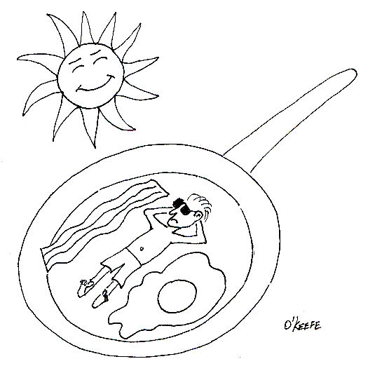
Last week we talked about convective heat transfer and how hot pavement in a parking lot gives up its heat to the environment. But how does the pavement get hot to begin with? This week we’ll discuss radiant heat transfer to find out. The sun is a huge nuclear furnace, separated from the earth by 93 million miles of space. The space between is just a vacuum, almost completely devoid of matter. Without contiguous solid or liquid matter between the two, heat transfer by conduction or convection can’t occur. The heat that we feel on earth is actually generated when surfaces here absorb electromagnetic energy waves emitted by the sun. Although these waves have traveled through millions of miles of space, they have not lost their punch. Our eyes perceive some of them as sunshine, but many others are not visible. But even if we can’t see them, our bodies often perceive them as heat. But radiant heat transfer isn’t a phenomenon exclusive to the sun. It can also occur when something is on fire. Intense fires can transmit tremendous amounts of radiant energy across significant distances. They can even cause combustible materials nearby to burst into flame without any direct contact being necessary. A line of sight between the source of heat and the receiving object is all that is required, and this is because radiation moves in straight lines, it can’t bend around corners. In order to calculate radiant heat transfer, we still must consider the temperature difference between the bodies, as well as the area of heat transfer, just as we did when considering the cases of conductive and convective heat transfer. But since there is no conduction or convection activity taking place, we need not concern ourselves with thermal conductivity or convection coefficients. Instead, we have to consider something called the Stefan-Boltzmann constant, a nifty little number that looks like this: 0.000000057 Watts/m2K4. It was discovered in 1879 by a scientist named Jozef Stefan. It was later derived by his student, Ludwig Boltzmann, in his work on thermodynamics and quantum mechanics. Now remember from our discussion last week the unit “K” means Kelvin (°C +273.15). Now, ideal radiant heat transfer problems involve calculations that need only consider the Stefan-Boltzmann constant. By “ideal,” I mean that there is perfect emission of radiation by one object and perfect absorption of that radiation by another. But reality is not typically so kind, and radiant heat transfer problems typically involve calculations that involve more than just the Stefan-Boltzmann constant. They involve additional calculations of terms like emissivity factors and geometric factors. What’s that? Read on. Emissivity factors relate to how well objects actually emit and absorb radiation compared to an ideal case. For example, a shiny object doesn’t absorb radiant energy as well as a dull, black object. Geometric factors are included in radiant heat transfer calculations to account for the shapes and relative orientation of the objects emitting and receiving radiation. For example, do you ever notice how the sun is hotter at noon than it is at sunset? Well, that’s because an object with a surface that’s parallel to the surface emitting radiation will receive more radiation than one that isn’t. Just to give you a basic idea of how radiant heat transfer calculations work, let’s consider an ideal situation. Suppose you own a store building with a flat roof. The store is right on the equator and it’s the vernal equinox. The roofing material is dull black, measures 20 meters by 10 meters, and it absorbs radiant energy like a sponge. But today is a dark, cloudy day, and the temperature of the roof is a cool 25°C. Now, at some point in your life I’m sure you’ve seen a documentary where scientists declared that the surface temperature of the sun is a blistering 5,400°C. Keeping this in mind, if the sun were to suddenly pop out of the clouds directly overhead at high noon, what would be the amount of radiant heat it would transfer to the roof? Well, according to Jozef Stefan, the radiant heat transfer rate can be calculated to be: Heat Flow = (The Stefan-Boltzmann Constant) x (The Area of the Roof) x ((The Sun’s Temperature)4 – (The Initial Roof Temperature)4) Now the terms we’ll need to plug into the heat flow calculation above are found as follows: The sun’s temperature is: 5,400°C + 273.15 = 5,673.15K. The temperature of the roof is: 25°C + 273.15 = 298.15K. The area of the roof is: 20 meters x 10 meters = 200 meters2. So, the heat transfer rate is: Heat Flow = (0.000000057 Watts/m2K4) x (200 m2) x ((5,673.15K) 4 – (298.15K) 4) = 11,808,605,250 Watts This would be the maximum rate of heat transfer that the roof could absorb at the instant the sun popped out of the clouds. From our example we can conclude that even in less than ideal conditions, radiant energy from the sun has the potential to generate tremendous amounts of heat on the surface of the earth. Much of this heat drives our weather as a result of convective heat transfer that takes place between the earth’s surface and our atmosphere. That wraps things up for our discussion of heat transfer in mechanical engineering. Next week we’ll talk about the importance of vibration analysis in design. Remember what happened to Jody Foster’s character in the movie Contact when the space/time device she was in began to shake violently? That’s the kind of thing vibration analysis seeks to correct! _________________________________________________________________ |
Posts Tagged ‘heat flow’
Heat Transfer in Mechanical Engineering, Part III, Radiation
Sunday, February 28th, 2010Heat Transfer in Mechanical Engineering, Part II, Convection
Sunday, February 21st, 2010|
Last week we talked about heat transfer by conduction, with an example that showed how heat flowed from hot to cold through a solid block of metal. This week we’ll focus on another method of heat transfer known as convection. Convection occurs when heat is transferred between a surface and a moving fluid. As with conduction, heat always wants to flow from a higher temperature to a lower temperature. There are two types of convective heat transfer, natural and forced. An example of natural convection would be hot air rising off a blacktop highway on a sunny summer day. The cool air near the ground picks up heat from the sun-baked blacktop. As the air heats, its density decreases and it gets lighter. The warmer, lighter air rises off the highway and more cool air rolls in to take its place. This creates a continuous natural airflow that removes heat from the blacktop. You can actually see this airflow as ripples in the air just above the highway. It produces a mirage effect and almost appears to be water on the highway, particularly on very hot days. In natural convection we are concerned with heat transfer between a surface and a fluid moving over that surface. To calculate the heat transfer, we need only consider the area of the surface and the temperature difference between the surface and the fluid. There is no material thickness to consider like we saw in last week’s conductive heat transfer example, where heat was moving through a solid object. So rather than working with a conductive heat transfer coefficient, we must work with a convective heat transfer coefficient, and our engineering reference guide will guide us to the correct convective coefficient to be used to calculate heat flow. With this said, we can calculate the natural convective heat flow to be: Heat Flow = (The Convective Heat Transfer Coefficient) x (The Area That The Heat Is Flowing Through) x (The Difference In Temperature) Now let’s go back to the blacktop to see how this all works. Suppose you have a parking lot and you want to know how much heat it is pumping into the atmosphere on a hot, sunny summer day with no wind. We must first determine the area of the lot, and we measure it out to be 100 meters by 100 meters. That’s 100 X 100, or 10,000 square meters of blacktop we’re talking about. We now measure the surface temperature of the blacktop and find it to be 65°C, but the air temperature near the ground away from any source of blacktop is a cool 30°C. Okay, so what is the heat transfer? First, you consult your friendly engineering reference manual. It tells you that the convective heat transfer coefficient is 15 Watts/meter2K for still air over a horizontal surface. The “K” represents temperature measured in degrees “Kelvin,” and this is calculated by simply adding 273.15 to any temperature measured in degrees Celsius, or °C. So, to get all of our units to match up in order to perform the calculation, the blacktop would be at a temperature of 65°C + 273.15 = 338.15K. The cool air would be at a temperature of 30°C + 273.15 = 303.15K. Our equation becomes: Heat Flow = (15 W/m2K) x (10,000 m2) x (338.15K – 303.15K) = 5,250,000 Watts We have calculated that the air in the atmosphere picks up heat energy from the parking lot pavement at a rate of over 5 million watts. This explains why it always seems to be warmer in cities compared to the surrounding countryside. The presence of dark asphalt pavement and dark roofing materials absorb heat from the sun like any dark surface will, and this heat buildup then dissipates into the surrounding atmosphere through the process of natural convection. The other type of convection, the forced type, is just as its name implies. It requires a powered device to move the fluid, that is to say, it does not rely on a natural source of energy like the sun. An example of forced convection can be found in a hair dryer, which uses a small blower to move air over an electric heating element. Another example of forced convection can be found in the water pump of your car. This pump circulates water through the engine, absorbing heat as it goes, and then gives that heat up to the air which is flowing over the radiator fins. This keeps the engine from overheating. Calculating heat transfer rates in forced convection problems can get extremely complicated, involving higher level mathematics and concepts of advanced fluid dynamics. Some problems are so complex they can only be solved with the aid of specially written computer programs, so an example problem would be beyond the scope of the basic discussions in this series of articles. Next week we’ll analyze how the sun, which is separated from Earth by 93 million miles of the vacuum that we call Outer Space, is able to heat our blacktop pavement up from so great a distance. It does this by the process of radiant heat transfer. _________________________________________________________________ |


