|
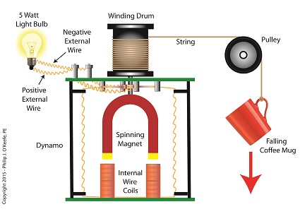
When acting as an engineering expert I’m often called upon to investigate incidents where energy converts from one form to another, a phenomenon that James Prescott Joule observed when he built his apparatus and performed his experiments with electricity. Today we’ll apply Joule’s findings to our own experiment with a coffee mug when we convert its kinetic energy into electrical energy and see how the units used to express that energy also change. We had previously calculated the kinetic energy contained within our falling coffee mug to be 4.9 kg • meter2/second2, also known as 4.9 Joules of energy, by using de Coriolis’ Kinetic Energy Formula. Now most of us don’t speak in terms of Joules of energy, but that’s easily addressed. As we learned in a previous blog on The Law of Conservation of Energy, all forms of energy are equivalent and energy can be converted from one form to another, and when it does, the unit of energy used to express it also changes. Let’s say we want to put our mug’s 4.9 Joules of kinetic energy to good use and power an electric light bulb. First we must first find a way of converting the mug’s kinetic energy into electrical energy. To do so, we’ll combine Joule’s apparatus with his dynamo, and connect the mug to this hybrid device with a string.
Converting Kinetic Energy to Electrical Energy As the mug falls its weight tugs on the string, causing the winding drum to rotate. When the drum rotates, the dynamo’s magnet spins, creating electrical energy. That’s right, all that’s required to produce electricity is a spinning magnet and coils of wire, as explained in my previous blog, Coal Power Plant Fundamentals – The Generator. Now we’ll connect a 5 Watt bulb to the dynamo’s external wires. The Watt is a unit of electrical energy named in honor of James Watt, a pioneer in the development of steam engines in the late 18th Century. Now it just so happens that 1 Watt of electricity is equal to 1 Joule of energy per a specified period of time, say a second. This relationship is expressed as Watt • second. Stated another way, 4.9 Joules converts to 4.9 Watt • seconds of electrical energy. Let’s see how long we can keep that 5 Watt bulb lit with this amount of energy. Mathematically this is expressed as, Lighting Time = (4.9 Watt • seconds) ÷ (5 Watts) = 0.98 seconds This means that if the mug’s kinetic energy was totally converted into electrical energy, it would provide enough power to light a 5 Watt bulb for almost 1 second. Next time we’ll see what happens to the 4.9 Joules of kinetic energy in our coffee mug when it hits the floor and becomes yet another form of energy. Copyright 2015 – Philip J. O’Keefe, PE Engineering Expert Witness Blog ____________________________________ |
Posts Tagged ‘kinetic energy’
Converting Kinetic Energy to Electrical Energy
Tuesday, November 3rd, 2015James Prescott Joule and the Joule Apparatus
Tuesday, October 6th, 2015|
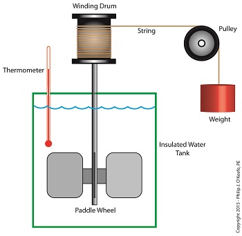
As an engineering expert I’ve often witnessed energy change forms, something our example coffee mug has been experiencing as it moves from a shelf to the floor. The mug’s various energies were proven to be mathematically equivalent, expressed as, 4.9 kg•meter2 /second2 , which is read as, “kilogram meter squared per second squared.” This mouthful led to the renaming of the measurement to the Joule, in honor of James Prescott Joule, a scientist who successfully demonstrated the interrelationship between different forms of energy. We’ll focus on one of his experiments, the Joule Apparatus, today. Back in the 1840s Joule built his Apparatus, a device which demonstrated the interrelationship between different forms of energy. The Joule Apparatus The Joule Apparatus consisted of a weight suspended by string over a pulley, which in turn was wound around a winding drum. As long as the drum remained stationary, the weight remained motionlessly suspended. While motionless, the weight’s potential energy lay latent within it, just as it had in our example coffee mug resting on a shelf. But when the pressure keeping the winding drum stationary was released, the weight was set free to fall, and its potential energy began converting to kinetic. In the process, the string the weight was attached to unwound from the drum, which caused the drum to turn and along with it the paddle wheel it was attached to. Joule’s Apparatus followed energy through many forms. From the quiet of potential energy to the kinetic energy demonstrated by the falling weight. The kinetic energy in turn was converted into mechanical energy, made manifest by the interaction between the moving drum and paddle wheel. The rotating paddles agitated the water, causing its temperature to rise. Observing this, Joule concluded that the mechanical energy of the spinning paddle wheel had been converted into heat energy, which temperature measurement proved was transferred into the water. Joule’s experiment thus proved the link between potential, kinetic, mechanical, and heat energies. Joule’s work paved the way to make possible the later development of a host of modern mechanical devices that also converted heat energy into mechanical energy, or vice versa. These devices include a car’s engine and your kitchen’s refrigerator. Next time we’ll see how Joule demonstrated a link between electrical and other forms of energy, including mechanical and heat. We’ll then use his discoveries to convert our falling coffee mug’s kinetic energy into yet another form. Copyright 2015 – Philip J. O’Keefe, PE Engineering Expert Witness Blog
____________________________________ |
Calculating Velocity — de Coriolis’ Kinetic Energy Formula
Monday, September 28th, 2015|
Last time we introduced Gaspard-Gustave de Coriolis’ formula to compute kinetic energy. Today we’ll use it to determine the speed of descent, or velocity, of the coffee mug we’ve been watching closely in the last few blogs. To calculate the mug’s velocity, we must bear in mind physicist Julius Robert von Mayer’s assertion that all forms of energy are interrelated, and in fact interchangeable, because energy can neither be created nor destroyed, it can only change forms. For a refresher, see The Law of Conservation of Energy. Let’s now put a practical spin on this concept and apply it to our coffee mug’s free fall to the floor. Once again, de Coriolis’ formula, KE = ½ × m × v2 (1) where m is the mass of our falling object and v its velocity. The ½ is an unchanging, constant term that’s present due to the mathematical Rules of Integration governing integral calculus. Calculus and its derivations are beyond the scope of this blog, but if you’re interested in pursuing this, follow this link to, The Physics Hypertextbook – Kinetic Energy. According to von Mayer’s Law, at the precise instant before the mug hits the floor its kinetic energy, KE, is equal to the potential energy, PE, it possessed when it rested passively on the shelf. Stated another way, the instant before the mug makes contact with the floor, all its potential energy will have been converted into kinetic. The mug’s PE was calculated previously to be equal to 4.9 kg • meter2/second2. See Computing Potential Energy for a review. Knowing this, the mathematical relationship between the mug’s potential and kinetic energies is expressed as, PE = KE = 4.9 kg • meter2/second2 (2) By substituting this mathematical representation for KE into equation (1) we arrive at, 4.9 kg • meter2/second2 = ½ × m × v2 (3) We also know the mug’s mass, m, to be equal to 2.6 kilograms, so integrating that into the right side of equation (3) it becomes, 4.9 kg • meter2/second2 = ½ × ( 0.25kg) × v2 (4) That leaves the mug’s velocity, v2, as the only remaining unknown term. We’ll use algebra to isolate this variable by dividing both sides of equation (4) by ½ × ( 0.25kg). (4.9 kg • meter2/second2) ÷ [½ × ( 0.25kg)] = v2 39.20 meter2/second2 = v2 Finally, we’ll take the square root of the equation to place it in terms of v. 6.26 meters/second = v The mug’s velocity an instant before impact equates to 6.26 meters/second, or almost 21 feet per second. Next time we’ll discuss a metric unit used to measure energy known as the Joule and discover the man behind it. Copyright 2015 – Philip J. O’Keefe, PE Engineering Expert Witness Blog ____________________________________ |
Calculation of the Effect of Machines — How to Calculate Kinetic Energy
Friday, September 18th, 2015|
Last time we introduced kinetic energy as the energy of movement. Today we’ll see how to calculate it, using French mathematician Gaspard-Gustave de Coriolis’ formula as set out in his textbook, Calculation of the Effect of Machines. We’ll then apply his formula to our example of a coffee mug falling from its shelf. Gaspard-Gustave de Coriolis’ book presented physics concepts, specifically the study of mechanics, in an accessible manner, without a lot of highbrow theory and complicated mathematics. His insights made complicated subjects easy to understand, and they were immediately put to use by engineers of his time, who were busily designing mechanical devices like steam engines during the early stages of the Industrial Revolution. Within its pages the mathematics of kinetic energy was presented in the scientific form that persists to present day. That formula is, KE = ½ × m × v2 where m is the moving object’s mass and v its velocity. In the case of our coffee mug, its kinetic energy will be zero so long as it remains motionless on the shelf. A human arm had lifted it to its perch against the force of gravity, thereby investing it with gravitational potential energy. If the mug was sent freefalling to the ground by the mischievous kitty, its latent potential energy would be realized and converted into the kinetic energy of motion. To illustrate, let’s say a mug with a mass equal to 0.25 kg rests on a shelf 2 meters above the floor. Its potential energy would then be equal to 4.9 kg • meter2/second2, as was computed in our previous blog, Computing Potential Energy. Once kitty nudges the mug from its perch and it begins to fall, its latent gravitational potential energy begins a conversion process from potential to kinetic energy. It will continue to convert into an amount of kinetic energy that’s precisely equal to the mug’s potential energy while at rest on the shelf, that is, 4.9 kg • meter2/second2. Upon impact with the floor, all the mug’s gravitational potential energy will have been converted into kinetic energy. Next time we’ll apply the Law of Conservation of Energy to the potential and kinetic energy formulas to calculate the mug’s velocity as it freefalls to the floor. Copyright 2015 – Philip J. O’Keefe, PE Engineering Expert Witness Blog ____________________________________
|
Willem Gravesande’s Experimentation on Kinetic Energy
Friday, September 11th, 2015|
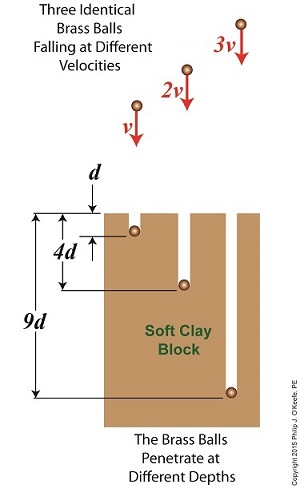
Last time we introduced The Law of Conservation of Energy, which holds that energy can neither be created nor destroyed. We then applied the concept to a mug resting on a shelf, brimming with latent gravitational potential energy. Today we’ll continue our discussion with a focus on kinetic energy and how Willem Gravesande’s experimentation contributed to our understanding of the subject. The concept of kinetic energy was first posited by mathematicians Gottfried Leibniz and Johann Bernoulli in the early 18th Century when they theorized that the energy of a moving object is a factor of its mass and speed. Their theory was later proven by Willem Gravesande, a Dutch lawyer, philosopher, and scientist. Gravesande conducted experiments in which he dropped identical brass balls into a soft clay block. See Figure 1. Figure 1 Figure 1 shows the results obtained when balls of the same mass m are dropped from various heights, resulting in different velocities as they fall and different clay penetrations. The ball on the left falls at velocity v and penetrates to a depth d. The center ball falls at twice the left ball’s velocity, or 2v, and penetrates four times as deep, or 4d. The right ball falls at three times the left ball’s velocity, 3v, and it penetrates nine times deeper, 9d. The results indicate an exponential increase in clay penetration, dependent on the balls’ speed of travel. In fact, all the kinetic energy that the balls exhibited during freefall was converted into mechanical energy from the instant they impacted the clay until their movement within it stopped. This change in forms of energy from kinetic to mechanical demonstrates what Julius Robert von Mayer had in mind when he derived his Law of Conservation of Energy. For a refresher on the subject, see last week’s blog, The Law of Conservation of Energy. As a result of his experimentation, Gravesande was able to conclude that the kinetic energy of all falling objects is a factor of their mass multiplied by their velocity squared, or m × v2. We’ll see next time how Gravesande’s work paved the way for later scientists to devise the actual formula used to calculate kinetic energy and then we’ll apply it all to our coffee mug falling from the shelf. Copyright 2015 – Philip J. O’Keefe, PE Engineering Expert Witness Blog ____________________________________
|
The Law of Conservation of Energy
Wednesday, September 2nd, 2015|
Last time we calculated the potential energy hidden within a coffee mug resting on a shelf. The concept of a passive object possessing energy may not be something all readers can identify with, but the secret behind that mug’s latent energy lies within The Law of Conservation of Energy, the topic we’ll be discussing today. Julius Robert von Mayer, a German physicist of the mid 19th Century, is the man behind the Law. He posited that energy cannot be created or destroyed, it can only be transferred from one object to another or converted from one form of energy to another. Forms of energy include potential, kinetic, heat, chemical, mechanical, and electrical, all of which have the ability to become another form of energy. Let’s take our coffee mug for example. Where did its potential energy come from? Ultimately, from the radiant energy emitted by the sun. The sun’s radiant energy was absorbed by plants and then converted to chemical energy through the process of photosynthesis, enabling them to grow. When they were later eaten by humans and other animals, the plants’ chemical energy became incorporated into their bodies’ cells, including the arm muscles used to lift the mug to the shelf. In the act of lifting the cup, the arm’s muscle cells converted their own chemical energy into mechanical energy. And because lifting a mug to a shelf is work, for some of us greater than others, some of the arm’s chemical energy became heat energy which was lost to the environment. Because of the elevated perch provided to the mug by the arm, which was in direct defiance of Earth’s gravitational pull, the arm muscles’ mechanical energy was transferred to the mug and converted to latent potential energy, because without that shelf to support it, the mug would fall to the ground. The mug’s potential energy would realize its full potential if it should be sent crashing to the floor, at which time it would become another form of energy. The mischievous orange kitty seems to have just that in mind. We’ll talk more about the mug’s potential energy being converted to other forms next time. Copyright 2015 – Philip J. O’Keefe, PE Engineering Expert Witness Blog ____________________________________
|
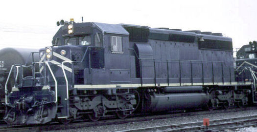
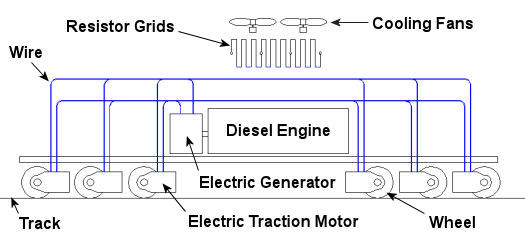
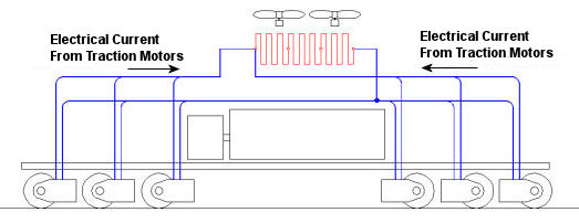
Diesel Locomotive Brakes
Sunday, June 6th, 2010|
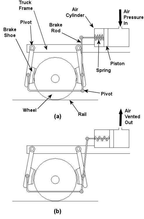
In the past few weeks we’ve taken a look at both mechanical and dynamic brakes. Now it’s time to bring the two together for unparalleled stopping performance. Have you ever wandered along a railroad track, hopping from tie to tie, daring a train to come roaring along and wondering if you could jump to safety in time? Many have, and many have lost the bet. That’s because a train, once set into motion, is one of the hardest things on Earth to bring to a stop. In this discussion, let’s focus on the locomotive. A large, six-axle variety is shown in Figure 1. Figure 1 – A Six-Axle Diesel-Electric Locomotive These massive iron horses are known in the industry as diesel-electric locomotives, and here’s why. As Figure 2 shows, diesel-electric locomotives are powered by huge diesel engines. Their engine spins an electrical generator which effectively converts mechanical energy into electrical energy. That electrical energy is then sent from the generator through wires to electric traction motors which are in turn connected to the locomotive’s wheels by a series of gears. In the case of a six-axle locomotive, there are six traction motors all working together to make the locomotive move. So how do you get this beast to stop? Figure 2 – The Propulsion System In A Six-Axle Diesel-Electric Locomotive You probably noticed in Figure 2 that there are resistor grids and cooling fans. As long as you’re powering a locomotive’s traction motors to move a train, these grids and fans won’t come into play. It’s when you want to stop the train that they become important. That’s when the locomotive’s controls will act to disconnect the traction motor wires running from the electrical generator and reconnect them to the resistor grids as shown in Figure 3 below. Figure 3 – The Dynamic Braking System In A Six-Axle Diesel Electric Locomotive The traction motors now become generators in a dynamic braking system. These motors take on the properties of a generator, converting the moving train’s mechanical, or kinetic, energy into electrical. The electrical energy is then moved by wires to the resistor grids where it is converted to heat energy. This heat energy is removed by powerful cooling fans and released into the atmosphere. In the process the train is robbed of its kinetic energy, causing it to slow down. Now you may be thinking that dynamic brakes do all the work, and this is pretty much true, up to a point. Although dynamic brakes may be extremely effective in slowing a fast-moving train, they become increasingly ineffective as the train’s speed decreases. That’s because as speed decreases, the traction motors spin more slowly, and they convert less kinetic energy into electrical energy. In fact, below speeds of about 10 miles per hour dynamic brakes are essentially useless. It is at this point that the mechanical braking system comes into play to bring the train to a complete stop. Let’s see how this switch from dynamic to mechanical dominance takes place. A basic mechanical braking system for locomotive wheels is shown in Figure 4. This system, also known as a pneumatic braking system, is powered by compressed air that is produced by the locomotive’s air pump. A similar system is used in the train’s railcars, employing hoses to move the compressed air from the locomotive to each car. Figure 4 – Locomotive Pneumatic Braking System In the locomotive pneumatic braking system, pressurized air enters an air cylinder. Once inside, the air bears against a spring-loaded piston, as shown in Figure 4(a). The piston moves, causing brake rods to pivot and clamp the brake shoes to the locomotive’s wheel with great force, slowing the locomotive. When you want to get the locomotive moving again, you vent the air out of the cylinder as shown in Figure 4(b). This takes the pressure off the piston, releasing the force from the brake shoes. The spring in the cylinder is now free to move the shoes away from the wheel so they can turn freely. We have now returned to the situation present in Figure 2, and the locomotive starts moving again. Next week we’ll talk about regenerative braking, a variation on the dynamic braking concept used in railway vehicles like electric locomotives and subway trains. _____________________________________________ |
Dynamic Brakes
Monday, May 31st, 2010|
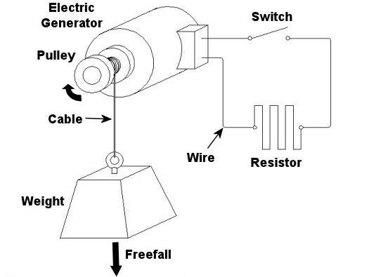
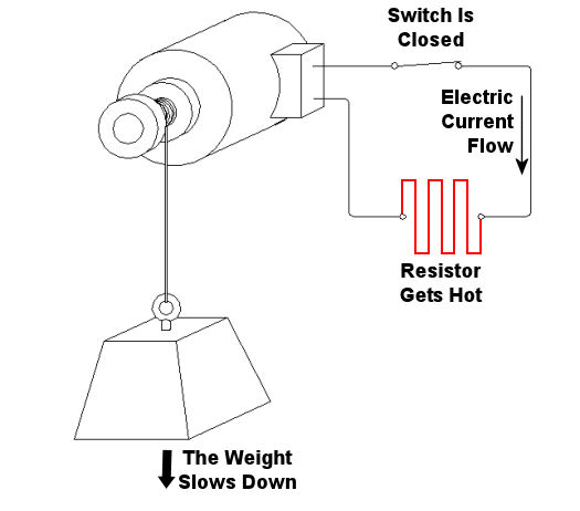
Last week we looked at how a mechanical brake stopped a rotating wheel by converting its mechanical energy, namely kinetic energy, into heat energy. This week, we’ll see how a dynamic brake works. Chances are you have directly benefited by a dynamic braking system the last time you rode in an elevator. But, to understand the basic principle behind an elevator’s dynamic brake system, let’s first take a look at the electric braking system in Figure 1 below. Figure 1 – A Simple Electric Braking System Here the brake consists of an electric generator wired via an open switch to an electrical component called a resistor. The weight is attached to a cable that is wound around a pulley on the generator’s shaft. As the weight freefalls, the cable unwinds on the pulley, causing the pulley to turn the generator’s shaft. Unlike last week’s mechanical brake which required a good deal of effort to employ, a dynamic braking system requires very little. All that needs to be done is to close a switch as shown in Figure 2 below. When the switch is closed, an electrical circuit is created where the resistor gets connected to the generator. The resistor does as its name implies: it resists (but doesn’t stop) the electrical current flowing through it from the generator. As the electrical current fights its way through the resistor to get back to the generator, the resistor gets hot like an electric heater. This heat is dissipated to the cooler surrounding air. At the same time, the weight begins to slow down in its descent. But how is this happening? The electric braking system can be thought of as an energy conversion process. We start out with the kinetic, or motion energy, of the freefalling weight. This kinetic energy is transmitted to the electrical generator by the cable, which spins the generator’s shaft as the cable unwinds. Electrical generators are machines that convert kinetic energy into electrical energy. This energy travels from the electric generator through wires and a closed switch to the resistor. In the process the resistor converts the electrical energy into heat energy. So, kinetic energy is drawn from the falling weight through the conversion process and leaves the process in the form of heat. As the falling weight is drained of kinetic energy, it slows down.
Figure 2 – Applying the Electric Brake Okay, now let’s get back to dynamic brakes on elevators. An elevator is attached by a cable to a hoist that is powered by an electric motor. When it’s time to stop at the desired floor, the automatic control system disconnects the elevator’s electric motor from its power source and turns the motor into a generator. The generator is then automatically connected to a resistor like the one shown in the electric brake above. The kinetic energy of the moving elevator is converted by the generator into electrical energy. The resistor converts the electrical energy into heat energy which is then dissipated into the surrounding environment. The elevator slows down in the process because it’s being robbed of kinetic energy. When the dynamic brake slows the elevator down enough, a mechanical brake is introduced, taking over to bring the elevator to a complete stop. This two-fold process serves to reduce wear and tear on the mechanical brake’s parts, lengthening the operational lifespan of the system as a whole. Next time, we’ll tie everything together and show how mechanical and dynamic brakes work together in a diesel locomotive. _____________________________________________ |
Brakes and Braking Systems
Sunday, May 23rd, 2010|
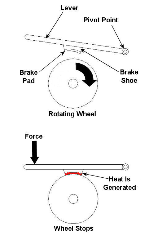
Imagine driving in your car, you’re traveling at a speed of 65 mph and you’re coming up on a curve. You depress your brake pedal to negotiate the turn, and nothing happens… Scenarios just like this one have been in the news quite often lately, brakes which just aren’t operating correctly. We’ve heard the tales of terror, recounted by those unfortunate individuals who have been placed in this situation, but have we reflected on just why their brakes might have failed? Put most simply, a brake is a device whose purpose is to stop a body in motion. This important task is accomplished by converting the kinetic energy (energy of motion) into heat energy. This can be accomplished by either of two methods, mechanically or electrically. In today’s blog we’ll focus on the mechanical aspect. A simple mechanical brake is shown in Figure 1 below. In this arrangement kinetic energy is converted into heat energy when force is applied to a lever, causing a brake shoe to meet up with a rotating wheel. The brake shoe has a pad attached to its surface that makes direct contact with the wheel, and when the two come together great friction is produced. It’s this friction that will ultimately stop the object in motion. Friction turns the kinetic energy into heat energy. Figure 1 – A Simple Mechanical Brake Friction at its simplest is a mechanical resistance to movement. Whenever two materials in motion come into contact with each other there is always some degree of friction. The extent to which friction is produced by their meeting is referred to as the “coefficient of friction.” The coefficient of friction varies according to the surface character of the materials coming in contact. For example, the coefficient of friction for the leather sole of your shoe on smooth ice is very low. This means you’ll do a lot of slipping when you’re trying to walk, and that’s because ice presents little friction to resist a smoothly soled shoe. But take this same shoe and apply it to the rough surface of concrete, and you’ll be walking quickly and efficiently. Coefficients of friction between different materials have been duly measured in laboratories and are tabulated for easy access in engineering reference books. Based on our simple example above, one would easily come to the conclusion that a high coefficient of friction is desirable when talking about brake shoes, specifically the one represented in Figure 1 above. The higher the coefficient of friction, the more the pad wants to grab the wheel, and the less force you will need to apply to the brake shoe to successfully come to a stop. That’s mechanical braking in a nutshell. Next time, we’ll focus on an electrical braking system known as a “dynamic brake.” _____________________________________________ |
