|
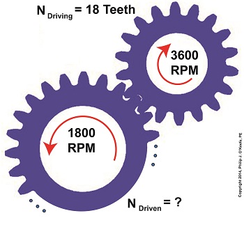
Last time we saw how a gear reduction does as its name implies, reduces the speed of the driven gear with respect to the driving gear within a gear train. Today we’ll see how to work the problem in reverse, so to speak, by determining how many teeth a driven gear must have within a given gear train to operate at a particular desired revolutions per minute (RPM). For our example we’ll use a gear train whose driving gear has 18 teeth. It’s mounted on an alternating current (AC) motor turning at 3600 (RPM). The equipment it’s attached to requires a speed of 1800 RPM to operate correctly. What number of teeth must the driven gear have in order to pull this off? If you’ve identified this to be a word problem, you’re correct. Let’s first review the gear ratio formulas introduced in my previous two articles: R = nDriving ÷ nDriven (1) R = NDriven ÷ NDriving (2) Our word problem provides us with enough information so that we’re able to use Formula (1) to calculate the gear ratio required: R = nDriving ÷ nDriven = 3600 RPM ÷ 1800 RPM = 2 This equation tells us that to reduce the speed of the 3600 RPM motor to the required 1800 RPM, we need a gear train with a gear ratio of 2:1. Stated another way, for every two revolutions of the driving gear, we must have one revolution of the driven gear. Now that we know the required gear ratio, R, we can use Formula (2) to determine how many teeth the driven gear must have to turn at the required 1800 RPM: R = 2 = NDriven ÷ NDriving 2 = NDriven ÷ 18 Teeth NDriven = 2 × 18 Teeth = 36 Teeth The driven gear requires 36 teeth to allow the gear train to operate equipment properly, that is to say, enable the gear train it’s attached to provide a speed reduction of 1800 RPM, down from the 3600 RPM that is being put out from the driving gear. But gear ratio isn’t just about changing speeds of the driven gear relative to the driving gear. Next time we’ll see how it works together with the concept of torque, thus enabling small motors to do big jobs.
_______________________________________ |
Posts Tagged ‘machine design engineer’
Gear Reduction Worked Backwards
Sunday, March 9th, 2014When Do You Need To Modify Gear Ratio?
Wednesday, February 19th, 2014|
Last time we saw how the involute profile of spur gear teeth ensures smooth contact between gears when they rotate. Today we’ll see why it’s important to be able to change the rotational speed of the driven gear in relation to that of the driving gear by modifying their gear ratio, the speeds at which gears move relative to one another. Why would we want to modify the rotational speeds of gears relative to one another? One reason is to compensate for the fact that alternating electric current (AC) motors drive most modern machinery, and these motors operate at a fixed speed determined by the 60 cycles per second frequency of electricity provided by the utility power grids of North America. By fixed speed I mean that the motor’s shaft revolves at a single, fixed rate. It can’t run any faster or slower. This is fine for some motorized applications, but not others. Basic machinery such as wood cutting saws, grinders, and blowers function well within the parameters of the AC motor’s fixed speed, because their working parts are intended to rotate at the same rate as the motor’s shaft. As a matter of fact, in this instance there’s often no need for a gear train, because the working parts can be connected directly to the motor’s shaft, and the machinery will be powered and function correctly. There are many instances however in which a fixed speed does not match the speed required for more complex machinery to correctly perform precise, specialized tasks. Take a machine tool meant to cut steel bars, for example. It has a rotating part meant to cut through the steel during machining, and to properly do so its cutting tool bit must turn at 400 revolutions per minute (RPM). If it turns any faster, the cut won’t be smooth and the tool bit will overheat and break due to increased friction. If the AC motor driving the machine tool turns at 1750 RPM, a common speed for such motors, then the tool bit will be turning at a much faster rate than the desired 400 RPM, and this presents a problem. To solve the problem we need only add a gear train between the motor and the part containing the tool bit, meaning, we must connect the gear train’s driving gear to the motor’s shaft and a driven gear to the part’s shaft. But in order for this arrangement to work a conversion must take place, that is, we must design the gear train to operate at a specific gear ratio. By gear ratio, I mean the speeds at which the two gears will rotate relative to one another. Next time we’ll introduce the gear ratio formulas that make it all work.
_______________________________________ |


