Last time we looked at my electric relay solution to a problem presented by a 120 volt alternating current (VAC) drive motor operating within an x-ray film processing machine. Now let’s see what happens when we press the button to set the microprocessor into operation.
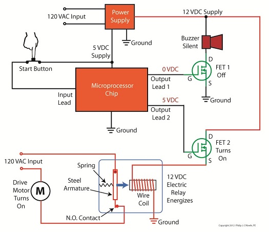
Figure 1Figure 1 shows that when the button is depressed, the computer program contained within the microprocessor chip goes into action, signaling the start of the control initiative. 5 volts direct current (VDC) is supplied to Output Lead 2, and FET 2 (Field Effect Transistor 2) becomes activated, which allows electric current from the 12 VDC supply to course into the 12 VDC electric relay, through the relay’s wire coil, then conclude its travel into electrical ground. The electric relay components, including a wire coil, steel armature, spring, and normally open (N.O.) contact, are shown within a blue box in our illustration. Current flow is represented by red lines. The control initiative passes from the microprocessor to FET 2, and then to the 12 VDC electric relay, just as the Olympic Torch is relayed through a system of runners. We learned in one of my previous articles on industrial control that when an electric relay coil is energized, electromagnetic attraction pulls its steel armature towards the wire coil and the N.O. electrical contact. In Figure 1 this attraction is represented by a blue arrow. With the N.O. contact closed the drive motor is connected to the 120 VAC input, and the motor is activated. Figure 2
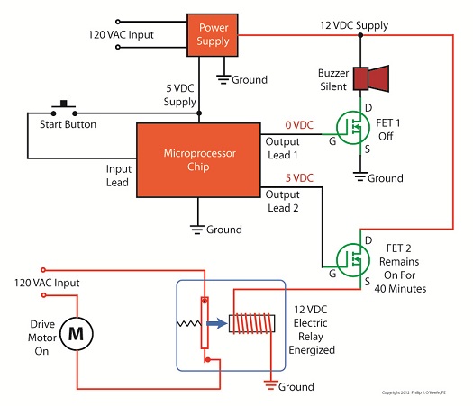
Figure 2 shows what happens after the button is depressed. The computer program is activated, directing the microprocessor chip to keep 5 VDC on Output Lead 2 and FET 2 while the prerequisite 40 minutes elapses. Thus the relay remains energized and the motor remains on during this time. Figure 3
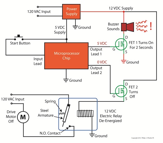
In Figure 3, at the end of the 40 minute countdown, the computer program applies 0 VDC to Output Lead 2. FET 2 then turns off the current flow to the relay and it begins to de-energize, causing the spring to pull the steel armature away from the N.O. contact and the 120 VAC power supply to be interrupted. The motor is deactivated. At the same time, the computer program applies 5 VDC to Output Lead 1 and FET 1 for 2 seconds. FET 1 turns on the flow of current through the buzzer, causing it to sound off and signal that the x-ray film processing machine is ready for use. Next time we’ll look at how transistors are used to regulate voltage within direct current power supplies like the one shown in Figure 3 above. ____________________________________________ |
Posts Tagged ‘machine’
Transistors – Digital Control Interface, Part V
Sunday, July 15th, 2012Tags: armature, buzzer, computer program, design, electric circuit, electric drive motor, electric relay, electronic control, electronics, engineering expert witness, FET, field effect transistor, forensic engineer, industrial control, machine, microprocessor chip, microprocessor control, MOSFET, motor control, normally open contact, output lead, power supply, pushbutton, spring, transistor, voltage regulator, wire coil, x-ray film processing machine
Posted in Engineering and Science, Expert Witness, Forensic Engineering, Innovation and Intellectual Property, Personal Injury, Product Liability | Comments Off on Transistors – Digital Control Interface, Part V
Industrial Control Basics – Manual Control
Monday, December 12th, 2011| You’ve probably heard the saying, “asleep at the switch.” It’s usually associated with some sort of disaster, found later to have been caused by human error. Someone wasn’t paying attention, and something very bad happened. The meltdown of the Soviet nuclear power plant Chernobyl in 1986 comes to mind. You may be surprised to learn that the saying has its origins in the world of industrial controls, or more specifically, manual controls, as we’ll see in this article.
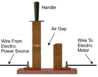
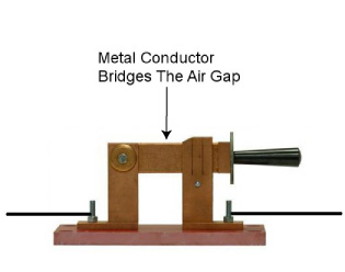
Last week when we opened our discussion on manual controls, we talked about how they work just as their name implies, that is, someone must manually press a button or throw a switch in order to initiate a factory operation. In other words, a manual control requires human intervention to initiate an action, such as pushing the start button. The machine will then continue to run until a person hits the stop button. Let’s go now on a virtual field trip into a telephone factory to see how a basic manual control system works. It has a conveyor belt operated by an electric motor, and this motor is connected by wires and a power switch to a 120 volt power source of alternating current. Figure 1 illustrates what we mean. It shows that when the power switch is in the open position, a physical air gap exists within the electrical circuit. This prevents electricity from flowing through the wire because electricity can’t jump over gaps. Figure 1 – Open Power Switch Enter a human into the scenario, someone who grabs the power switch handle and manually closes it, eliminating the air gap. See Figure 2. Figure 2 – Closed Power Switch When the power switch is closed, a metal conductor bridges the gap, causing electricity to flow through the metal conductor to the electric motor in the circuit. This brings life to the conveyor belt. As long as the power switch remains closed, the conveyor belt will continue to operate. That’s it, that’s a basic manual control system. It’s simple to operate, but it does have one major flaw. It requires constant monitoring by a human. Aside from opening and closing a power switch, humans are required to monitor operations, in case something goes wrong. The operator watching over an industrial machine performs the same function as the pilot on a plane, that is, to start-stop operations, and to intervene in case of an emergency. Computers fly modern jets. Pilots serve as trouble shooters when the unanticipated disaster situation occurs, because computers can’t yet creatively problem solve. Next time we’ll introduce the element of an automatic control system, which will virtually eliminate the need for human intervention and with it human error. ____________________________________________ |
Tags: air gap, alternating current, asleep at the switch, assembly line, control system, conveyor belt, electricity, electricity flow, engineering expert witness, factory, forensic engineer, industrial controls, machine, manual control, metal conductor, motor, operator, power plant, power source, power switch, production line, start button, stop button, telephone, wire
Posted in Engineering and Science, Expert Witness, Forensic Engineering, Innovation and Intellectual Property, Personal Injury, Product Liability, Professional Malpractice | Comments Off on Industrial Control Basics – Manual Control
