|
When acting as an engineering expert I’m often called upon to investigate incidents where energy converts from one form to another, a phenomenon that James Prescott Joule observed when he built his apparatus and performed his experiments with electricity. Today we’ll apply Joule’s findings to our own experiment with a coffee mug when we convert its kinetic energy into electrical energy and see how the units used to express that energy also change. We had previously calculated the kinetic energy contained within our falling coffee mug to be 4.9 kg • meter2/second2, also known as 4.9 Joules of energy, by using de Coriolis’ Kinetic Energy Formula. Now most of us don’t speak in terms of Joules of energy, but that’s easily addressed. As we learned in a previous blog on The Law of Conservation of Energy, all forms of energy are equivalent and energy can be converted from one form to another, and when it does, the unit of energy used to express it also changes. Let’s say we want to put our mug’s 4.9 Joules of kinetic energy to good use and power an electric light bulb. First we must first find a way of converting the mug’s kinetic energy into electrical energy. To do so, we’ll combine Joule’s apparatus with his dynamo, and connect the mug to this hybrid device with a string.
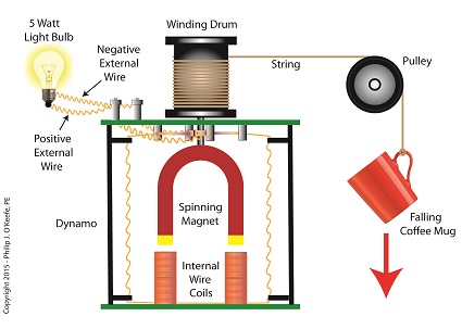
Converting Kinetic Energy to Electrical Energy As the mug falls its weight tugs on the string, causing the winding drum to rotate. When the drum rotates, the dynamo’s magnet spins, creating electrical energy. That’s right, all that’s required to produce electricity is a spinning magnet and coils of wire, as explained in my previous blog, Coal Power Plant Fundamentals – The Generator. Now we’ll connect a 5 Watt bulb to the dynamo’s external wires. The Watt is a unit of electrical energy named in honor of James Watt, a pioneer in the development of steam engines in the late 18th Century. Now it just so happens that 1 Watt of electricity is equal to 1 Joule of energy per a specified period of time, say a second. This relationship is expressed as Watt • second. Stated another way, 4.9 Joules converts to 4.9 Watt • seconds of electrical energy. Let’s see how long we can keep that 5 Watt bulb lit with this amount of energy. Mathematically this is expressed as, Lighting Time = (4.9 Watt • seconds) ÷ (5 Watts) = 0.98 seconds This means that if the mug’s kinetic energy was totally converted into electrical energy, it would provide enough power to light a 5 Watt bulb for almost 1 second. Next time we’ll see what happens to the 4.9 Joules of kinetic energy in our coffee mug when it hits the floor and becomes yet another form of energy. Copyright 2015 – Philip J. O’Keefe, PE Engineering Expert Witness Blog ____________________________________ |
Posts Tagged ‘magnet’
Converting Kinetic Energy to Electrical Energy
Tuesday, November 3rd, 2015Industrial Control Basics – Introduction to Electric Relays
Tuesday, January 3rd, 2012| I’ve always considered science to be cool. Back in the 5th grade I remember fondly leafing through my science textbook, eagerly anticipating our class performing the experiments, but we never did. For some reason my teacher never took the time to demonstrate any. Undeterred, I proceeded on my own.
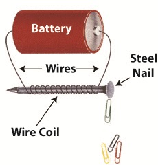
I remember one experiment particularly well where I took a big steel nail and coiled wire around it. When I hooked a battery up to the wires, as shown in Figure 1 below, electric current flowed from the battery through the wire coil. This set up a magnetic field in the steel nail, thereby creating an electromagnet. My electromagnet was strong enough to pick up paper clips, and I took great pleasure in repeatedly picking them up, then watching them unattach and fall quickly away when the wires were disconnected from the battery. Figure 1
Little did I know then that the electromagnet I had created was similar to an important part found within electrical relays used in many industrial control systems. An example of one of these relays is shown in Figure 2. Figure 2
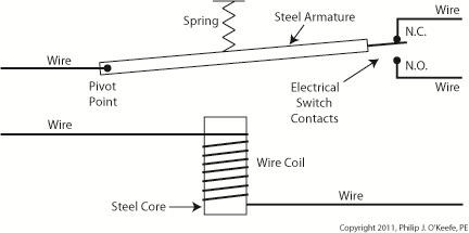
So, what’s in the little plastic cube? Well, a relay is basically an electric switch, similar to the ones we’ve discussed in the past few weeks, the major difference being that it is not operated directly by human hands. Rather, it’s operated by an electromagnet. Let’s see how this works by examining a basic electrical relay, as shown in Figure 3. Figure 3
The diagram in Figure 3 shows a basic electric relay constructed of a steel core with a wire coil wrapped around it, similar to the electromagnet I constructed in my 5th grade experiment. If the coil’s wires are not hooked up to a power source, a battery for example, no electric current will flow through it. When there is no current the coil and steel core are not magnetic. For purposes of our illustration and in accordance with industrial control parlance, this is said to be this relay’s “normal state.” Next to the steel core there is a movable steel armature, a kind of lever, which is attached to a spring. On one end of the armature is a pivot point, on the other end is a set of electrical switch contacts. When the relay is in its normal state, the spring’s tension holds the armature against the “normally closed,” or N.C., contact. If electric current is applied to the wire leading to the pivot point on the armature while in this state, it will be caused to flow on a continuous path through the armature and the N.C. contact, then out through the wire leading from the N.C. contact. In our illustration, since the armature does not touch the N.O. contact, an air gap is created that prevents electric current from traveling through the contact from the armature. Next week we’ll see how these parts come into play within a relay when electric current flows through the coil, turning it into an electromagnet. ____________________________________________ |


