Posts Tagged ‘mechanical energy’
Monday, September 25th, 2017
|
What came first? The wheel or the flywheel? Archeologists have been debating this question for decades. One thing is certain, they both date back to prehistoric times.
What Came First? The Wheel or the Flywheel?
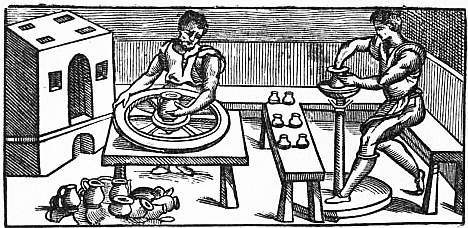
One of the oldest flywheel discoveries was a potter’s wheel, used to make pottery. It’s a turntable made of stone or heavy wood that’s connected to a massive wheel by a spinning shaft. Once the potter got the flywheel spinning with his hand or foot, the wheel’s heavy weight kept it in virtual perpetual motion, allowing the potter to concentrate on forming the clay he shaped with his hands.
A potter’s wheel, or any other flywheel for that matter, takes a lot of initial effort to put into motion. In other words, the potter must put a lot of his own muscles’ mechanical energy into the flywheel to get it moving. That’s because its sheer weight binds it to the Law of Inertia and makes it want to stay at rest.
But once the flywheel is in motion, the potter’s mechanical energy input is transformed into kinetic energy, the energy of motion. The kinetic energy the potter produces by his efforts results in surplus energy stored within the flywheel. Hence, the flywheel serves as a kinetic energy storage device, similar to a battery which stores electrical energy. As long as the flywheel remains in motion, this stored energy will be used to keep the turntable spinning, which results in no additional mechanical energy needing to be exerted by the potter while forming pots.
The flywheel’s stored energy also makes it hard to stop once it’s in motion. But eventually the frictional force between the potter’s hands and the clay he works drains off all stored kinetic energy.
Since the Industrial Revolution flywheels have been used to store kinetic energy to satisfy energy demands and provide a continuous output of power, which increases mechanical efficiency.
Next time we’ll begin our exploration into the science behind flywheels and see how they’re used in diverse engineering applications.
Copyright 2017 – Philip J. O’Keefe, PE
Engineering Expert Witness Blog
____________________________________ |
Tags: energy storage, engineering, flywheel, frictional force, inertia, kinetic energy, mechanical energy
Posted in Engineering and Science, Expert Witness, Forensic Engineering, Innovation and Intellectual Property, Personal Injury, Product Liability | Comments Off on What Came First? The Wheel or the Flywheel?
Friday, October 16th, 2015
|
In my work as an engineering expert I’ve dealt with all forms of energy, just as we’ve watched James Prescott Joule do. He constructed his Joule Apparatus specifically to demonstrate the connection between different forms of energy. Today we’ll see how he furthered his discoveries by building a prototype power plant capable of producing electricity, a device which came to be known as Joule’s Experiment With Electricity.

Joule’s Experiment With Electricity
As the son of a wealthy brewer, Joule had been fascinated by electricity and the possibility of using it to power his family’s brewery and thereby boost production. To explore the possibilities, he went beyond the Apparatus he had built earlier and built a device which utilized electricity to power its components. The setup for Joule’s experiment with electricity is shown here.
Coal was used to bring water inside a boiler to boiling point, which produced steam. The steam’s heat energy then flowed to a steam engine, which in turn spun a dynamo, a type of electrical generator.
Tracing the device’s energy conversions back to their roots, we see that chemical energy contained within coal was converted into heat energy when the coal was burned. Heat energy from the burning coal caused the water inside the boiler to rise, producing steam. The steam, which contained abundant amounts of heat energy, was supplied to a steam engine, which then converted the steam’s heat energy into mechanical energy to set the engine’s parts into motion. The engine’s moving parts were coupled to a dynamo by a drive belt, which in turn caused the dynamo to spin.
Next time we’ll take a look inside the dynamo and see how it created electricity and led to another of Joule’s discoveries being named after him.
Copyright 2015 – Philip J. O’Keefe, PE
Engineering Expert Witness Blog
____________________________________ |
Tags: boiler expert witness, dynamo, electric current, electric current induction, electrical energy, electrical engineering expert witness, electrical generator expert witness, electrical resistance of wires, engineering expert witness, forensic engineer, heat energy, James Prescott Joule, Joule Heating Effect, magnetic field, mechanical energy, mechanical engineering expert witness, power engineering expert witness, power plant, power plant engineering expert witness, steam, wire size
Posted in Engineering and Science, Expert Witness, Forensic Engineering, Innovation and Intellectual Property, Personal Injury, power plant training, Product Liability | Comments Off on Joule’s Experiment With Electricity
Tuesday, October 6th, 2015
|
As an engineering expert I’ve often witnessed energy change forms, something our example coffee mug has been experiencing as it moves from a shelf to the floor. The mug’s various energies were proven to be mathematically equivalent, expressed as, 4.9 kg•meter2 /second2 , which is read as, “kilogram meter squared per second squared.” This mouthful led to the renaming of the measurement to the Joule, in honor of James Prescott Joule, a scientist who successfully demonstrated the interrelationship between different forms of energy. We’ll focus on one of his experiments, the Joule Apparatus, today.
Back in the 1840s Joule built his Apparatus, a device which demonstrated the interrelationship between different forms of energy.

The Joule Apparatus
The Joule Apparatus consisted of a weight suspended by string over a pulley, which in turn was wound around a winding drum. As long as the drum remained stationary, the weight remained motionlessly suspended. While motionless, the weight’s potential energy lay latent within it, just as it had in our example coffee mug resting on a shelf.
But when the pressure keeping the winding drum stationary was released, the weight was set free to fall, and its potential energy began converting to kinetic. In the process, the string the weight was attached to unwound from the drum, which caused the drum to turn and along with it the paddle wheel it was attached to.
Joule’s Apparatus followed energy through many forms. From the quiet of potential energy to the kinetic energy demonstrated by the falling weight. The kinetic energy in turn was converted into mechanical energy, made manifest by the interaction between the moving drum and paddle wheel. The rotating paddles agitated the water, causing its temperature to rise. Observing this, Joule concluded that the mechanical energy of the spinning paddle wheel had been converted into heat energy, which temperature measurement proved was transferred into the water. Joule’s experiment thus proved the link between potential, kinetic, mechanical, and heat energies.
Joule’s work paved the way to make possible the later development of a host of modern mechanical devices that also converted heat energy into mechanical energy, or vice versa. These devices include a car’s engine and your kitchen’s refrigerator.
Next time we’ll see how Joule demonstrated a link between electrical and other forms of energy, including mechanical and heat. We’ll then use his discoveries to convert our falling coffee mug’s kinetic energy into yet another form.
Copyright 2015 – Philip J. O’Keefe, PE
Engineering Expert Witness Blog
____________________________________ |
Tags: electrical energy, energy engineer, energy of falling objects, engineering expert witness, forensic engineer, forms of energy, James Prescott Joule, Joule Apparatus, Joule energy unit, Joule's experiments, kinetic energy, mechanical energy, physics of falling objects, potential energy, work
Posted in Engineering and Science, Expert Witness, Forensic Engineering, Innovation and Intellectual Property, Personal Injury, Product Liability | Comments Off on James Prescott Joule and the Joule Apparatus
Friday, September 18th, 2015
|
Last time we introduced kinetic energy as the energy of movement. Today we’ll see how to calculate it, using French mathematician Gaspard-Gustave de Coriolis’ formula as set out in his textbook, Calculation of the Effect of Machines. We’ll then apply his formula to our example of a coffee mug falling from its shelf.
Gaspard-Gustave de Coriolis’ book presented physics concepts, specifically the study of mechanics, in an accessible manner, without a lot of highbrow theory and complicated mathematics. His insights made complicated subjects easy to understand, and they were immediately put to use by engineers of his time, who were busily designing mechanical devices like steam engines during the early stages of the Industrial Revolution.
Within its pages the mathematics of kinetic energy was presented in the scientific form that persists to present day. That formula is,
KE = ½ × m × v2
where m is the moving object’s mass and v its velocity.
In the case of our coffee mug, its kinetic energy will be zero so long as it remains motionless on the shelf. A human arm had lifted it to its perch against the force of gravity, thereby investing it with gravitational potential energy. If the mug was sent freefalling to the ground by the mischievous kitty, its latent potential energy would be realized and converted into the kinetic energy of motion.

To illustrate, let’s say a mug with a mass equal to 0.25 kg rests on a shelf 2 meters above the floor. Its potential energy would then be equal to 4.9 kg • meter2/second2, as was computed in our previous blog, Computing Potential Energy.
Once kitty nudges the mug from its perch and it begins to fall, its latent gravitational potential energy begins a conversion process from potential to kinetic energy. It will continue to convert into an amount of kinetic energy that’s precisely equal to the mug’s potential energy while at rest on the shelf, that is, 4.9 kg • meter2/second2. Upon impact with the floor, all the mug’s gravitational potential energy will have been converted into kinetic energy.
Next time we’ll apply the Law of Conservation of Energy to the potential and kinetic energy formulas to calculate the mug’s velocity as it freefalls to the floor.
Copyright 2015 – Philip J. O’Keefe, PE
Engineering Expert Witness Blog
____________________________________
|
Tags: Calculation of the Effect of Machines, engineering expert witness, engines, falling objects, Gaspard-Gustave de Coriolis, kinetic energy, machinery, mass, mechanical energy, mechanical engineer, mechanics, physics, potential energy, velocity
Posted in Engineering and Science, Expert Witness, Forensic Engineering, Innovation and Intellectual Property, Personal Injury, Product Liability | Comments Off on Calculation of the Effect of Machines — How to Calculate Kinetic Energy
Friday, September 11th, 2015
|
Last time we introduced The Law of Conservation of Energy, which holds that energy can neither be created nor destroyed. We then applied the concept to a mug resting on a shelf, brimming with latent gravitational potential energy. Today we’ll continue our discussion with a focus on kinetic energy and how Willem Gravesande’s experimentation contributed to our understanding of the subject.
The concept of kinetic energy was first posited by mathematicians Gottfried Leibniz and Johann Bernoulli in the early 18th Century when they theorized that the energy of a moving object is a factor of its mass and speed. Their theory was later proven by Willem Gravesande, a Dutch lawyer, philosopher, and scientist.
Gravesande conducted experiments in which he dropped identical brass balls into a soft clay block. See Figure 1.

Figure 1
Figure 1 shows the results obtained when balls of the same mass m are dropped from various heights, resulting in different velocities as they fall and different clay penetrations. The ball on the left falls at velocity v and penetrates to a depth d. The center ball falls at twice the left ball’s velocity, or 2v, and penetrates four times as deep, or 4d. The right ball falls at three times the left ball’s velocity, 3v, and it penetrates nine times deeper, 9d. The results indicate an exponential increase in clay penetration, dependent on the balls’ speed of travel.
In fact, all the kinetic energy that the balls exhibited during freefall was converted into mechanical energy from the instant they impacted the clay until their movement within it stopped. This change in forms of energy from kinetic to mechanical demonstrates what Julius Robert von Mayer had in mind when he derived his Law of Conservation of Energy. For a refresher on the subject, see last week’s blog, The Law of Conservation of Energy.
As a result of his experimentation, Gravesande was able to conclude that the kinetic energy of all falling objects is a factor of their mass multiplied by their velocity squared, or m × v2.
We’ll see next time how Gravesande’s work paved the way for later scientists to devise the actual formula used to calculate kinetic energy and then we’ll apply it all to our coffee mug falling from the shelf.
Copyright 2015 – Philip J. O’Keefe, PE
Engineering Expert Witness Blog
____________________________________
|
Tags: falling objects, forensic engineer, Gottfried Leibniz, impact, Johann Bernoulli, Julius Robert von Mayer, kinetic energy, mass, mechanical energy, mechanical engineering expert witness, penetration, potential energy, velocity, Willem Gravesande
Posted in Engineering and Science, Expert Witness, Forensic Engineering, Innovation and Intellectual Property, Personal Injury, Product Liability, Professional Malpractice | Comments Off on Willem Gravesande’s Experimentation on Kinetic Energy
Wednesday, September 2nd, 2015
|
Last time we calculated the potential energy hidden within a coffee mug resting on a shelf. The concept of a passive object possessing energy may not be something all readers can identify with, but the secret behind that mug’s latent energy lies within The Law of Conservation of Energy, the topic we’ll be discussing today.
Julius Robert von Mayer, a German physicist of the mid 19th Century, is the man behind the Law. He posited that energy cannot be created or destroyed, it can only be transferred from one object to another or converted from one form of energy to another. Forms of energy include potential, kinetic, heat, chemical, mechanical, and electrical, all of which have the ability to become another form of energy.
Let’s take our coffee mug for example. Where did its potential energy come from? Ultimately, from the radiant energy emitted by the sun. The sun’s radiant energy was absorbed by plants and then converted to chemical energy through the process of photosynthesis, enabling them to grow. When they were later eaten by humans and other animals, the plants’ chemical energy became incorporated into their bodies’ cells, including the arm muscles used to lift the mug to the shelf.
In the act of lifting the cup, the arm’s muscle cells converted their own chemical energy into mechanical energy. And because lifting a mug to a shelf is work, for some of us greater than others, some of the arm’s chemical energy became heat energy which was lost to the environment.
Because of the elevated perch provided to the mug by the arm, which was in direct defiance of Earth’s gravitational pull, the arm muscles’ mechanical energy was transferred to the mug and converted to latent potential energy, because without that shelf to support it, the mug would fall to the ground. The mug’s potential energy would realize its full potential if it should be sent crashing to the floor, at which time it would become another form of energy. The mischievous orange kitty seems to have just that in mind.

We’ll talk more about the mug’s potential energy being converted to other forms next time.
Copyright 2015 – Philip J. O’Keefe, PE
Engineering Expert Witness Blog
____________________________________
|
Tags: chemical energy, engineering expert witness, falling objects, gravity, kinetic energy, law of conservation of energy, mechanical energy, potential energy, radiant energy, work
Posted in Engineering and Science, Expert Witness, Forensic Engineering, Innovation and Intellectual Property, Personal Injury, Product Liability | Comments Off on The Law of Conservation of Energy
Tuesday, April 29th, 2014
|
We’ve been discussing torque and how it enables more power to be available to applications such as loosening tight nuts with a wrench. Now we’ll see how those same principles apply to another application, a simple gear train.
To review, the torque formula is,
Torque = Distance × Force × sin(ϴ)
where, Distance and Force are vector magnitudes and ϴ is the angle formed between them.

Referring to the gear train illustration above, we see that Force and Distance vectors are present, just as they had been in our previous wrench/nut example. But instead of torque being created by way of force that’s applied to a wrench, things are reversed, and it’s the torque that creates the force.
You see, in the wrench/nut example, the force applied to the wrench handle created torque on the nut. In our present gear train example, the torque applied to the motor shaft is created by an electric motor exerting pressure upon the motor shaft, which in turn exerts a force upon the driving gear teeth. The driving gear is also attached to this shaft, so torque causes the driving gear to rotate along with the motor. This rotation results in a force being exerted at the point where the teeth of the driving gear mesh with the teeth of the driven gear. In other words, in the wrench/nut example force created torque, while in the present example torque creates a force.
The gear train has a pivot point, as there was in our wrench/nut example, but this time it’s located at the center of the motor shaft rather than at the center of a nut. The pivot point in both examples is where the action takes place. The motor’s shaft and driving gear rotate around it, just as the wrench jaws and handle rotated around the nut’s pivot point.
In both examples, the Distance vectors extend out from the pivot points to meet up with the Force vector’s path. In the gear train example, this Force vector path is called a line of action, as introduced earlier in this blog series. This line of action passes through to the point where the driving and driven gear teeth mesh. The force acting upon that point causes the gears in the gear train to rotate, and as they turn mechanical energy is transferred from the motor to whatever machinery component is attached to the shaft of the driven gear. The powered component will then be able to perform useful work such as cutting lumber, mixing frosting for a cake, drilling holes in steel, or propelling vehicles.
You will note that there is an angle ϴ which exists between the Distance and Force vectors. Since we have a pivot point, a Force vector, a Distance vector, and an angle ϴ, we are able to apply the torque formula to gear trains exactly as we did in our wrench/nut example. We can then use that formula to calculate how torque is transmitted between gears in the train.
Next time we’ll examine the distance and force vectors in a simple gear train.
_______________________________________
|
Tags: distance vector, driven gear, driving gear, engineering expert witness, force, force vector, forensic engineer, gear expert witness, gear teeth, gear teeth mesh, gear train, line of action, machine design, machinery, mechanical design, mechanical energy, mechanical engineer, nut, pivot point, torque, torque formula, wrench
Posted in Engineering and Science, Expert Witness, Forensic Engineering, Innovation and Intellectual Property, Personal Injury, Product Liability | Comments Off on Torque and Force
Monday, January 27th, 2014
|
Last time we learned that the geometric shape specific to spur gear teeth is known as an involute profile. Today we’ll look at the geometry behind this profile and the very specific place at which gear teeth meet, known as the point of contact.
The transmission of mechanical energy between meshed gears may seem on its face to be straightforward, after all their gears are interlaced and interact with one another. But their interaction involves some rather complex geometry, because forces are directed in a peculiar fashion between the teeth of the driving and driven gears. Let’s consider the following illustration to get a better understanding.
 Meshed Gear Tooth Geometry
As we learned previously in this series, the pitch circle of a gear is an imaginary arc passing through each tooth between their top and bottom lands. The pitch circles of the driving and driven gears are represented by heavy red dashed lines in the illustration.
To ensure proper alignment and smooth action between gear teeth during rotation, the gears are spaced so that their pitch circles just meet but never intersect. This specific point is known as the point of contact. It is the only point at which gears will come into actual physical contact with one another, and it provides just enough contact so that when the driving gear turns in one direction, say clockwise, its teeth exert pressure upon the driven gear teeth, forcing it to move in the opposite direction, counterclockwise.
The forces which come into play at the point of contact are represented in the illustration by a black dot with oppositional blue arrows extending from it. These arrows represent the opposing mechanical forces, F1 and F2 , which act upon the teeth when they make contact.
We’ll learn more about the effect of those forces next time when we follow a locomotive from a stationary position into one of movement.
_______________________________________ |
Tags: driven gear, driving gear, engineering expert witness, forces, forensic engineer, gear geometry, gear rotation, gear technology, gear teeth, gear train, gears, involute profile, locomotive, mechanical energy, mechanical forces, meshed gears, pitch circle, point of contact, spur gear, tooth profile
Posted in Engineering and Science, Expert Witness, Forensic Engineering, Innovation and Intellectual Property, Personal Injury, Product Liability | Comments Off on Meshed Gear Teeth and Their Point of Contact
Sunday, January 19th, 2014
|
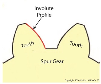
Last time we learned how spur gears mesh together to form a gear train and we examined a train consisting of just two gears, one being the driving gear, the other the driven gear. Today we’ll take a look at the geometry behind the smooth functioning of modern spur gear teeth when we identify their peculiar shape to be that of an involute curve.
The curved profile of spur gear teeth conforms to a type of mathematical curve found in geometry known as an involute. The involute profile of a spur gear tooth is shown in red below.

The mathematical notion of the involute was first presented in 1673 by Dutch mathematician Christiaan Huygens, in his book, Horologium Oscillatorium. Huygens’ book presents his studies on clock pendulums and the applied mathematics he used in an effort to predict their often erratic motion on ships at sea. His book ultimately dealt with far more than this, resulting in a treatise on the mathematical properties of the involutes of curves.
To see how an involute curve is formed, we’ll conduct a simple experiment. One end of string is attached with a tack to a circular object, like the yellow rod shown in the following illustration. The other end of string has a red ball attached to it.
 Forming An Involute Curve If we grab the ball and pull the string taught while wrapping the string around the rod, the ball’s path will form an involute curve due to the incremental shortening of the string that occurs as it wraps around the rod.
Next time we’ll see how the involute profile of gear teeth contributes to efficient mechanical energy transmission in gear trains.
_______________________________________ |
Tags: axle, Chritiaan Huygens, driven gear, driving gear, electric motor, engine, engineering expert witness, forensic engineer, gear expert, gear teeth, gear train, gears, gears mesh, involute, involute curve, locomotive, mechanical device, mechanical energy, mechanical engineering expert, mesh, powering device, railroad expert witness, shaft, spur gears, traction motor, train, wheels
Posted in Engineering and Science, Expert Witness, Forensic Engineering, Innovation and Intellectual Property, Personal Injury, Product Liability | Comments Off on Spur Gear Tooth Geometry and the Involute Curve
Monday, January 13th, 2014
|
Last time we covered the basic terminology of spur gears. Today we’ll see how they interact with one another to form a gear train, such as the one depicted below.
 Meshing Spur Gears Form A Gear Train A gear train is formed when the teeth of two or more gears mesh and work together for the purpose of powering a mechanical device.
A gear train can consist of as little as two gears, but trains can be so large as to contain dozens of gears, depending on the complexity of the device they are powering. But no matter how many gears are employed, there are certain key features that are shared by every gear train assembly. First, one gear within the train must be attached to a shaft rotated by a source of mechanical energy, such as an engine or electric motor. This gear is called the driving gear.
The second requirement of a gear train is that at least one gear other than the driving gear is mounted to the shaft of a rotating machine part. This gear is called the driven gear.
 Locomotive Gear Train Consisting Of Two Gears The illustration above shows an exploded view of a locomotive gear train assembly consisting of two gears. The driving gear is mounted to the shaft of an electric traction motor. The driven gear is mounted to the locomotive’s axle.
When a motor is attached to the axle, the two gears mesh together. The traction motor converts electrical energy into mechanical energy, which is supplied to the driving gear via the spinning motor’s shaft. The teeth of the driving gear then transmit the motor’s mechanical energy to the teeth of the driven gear, which then turn the locomotive’s wheels. It’s just one of countless operations that can be performed with gear train assemblies.
Next time we’ll examine the geometry behind modern spur gear tooth design.
_______________________________________ |
Tags: axle, driven gear, driving gear, electric motor, engine, engineering expert witness, forensic engineer, gear expert, gear teeth, gear train, gears, gears mesh, locomotive, mechanical device, mechanical energy, mechanical engineering expert, mesh, powering device, railroad expert witness, shaft, spur gears, traction motor, train, wheels
Posted in Engineering and Science, Expert Witness, Forensic Engineering, Innovation and Intellectual Property, Personal Injury, Product Liability | Comments Off on Gear Trains


