|
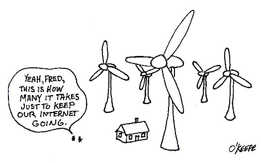
The last few weeks we’ve been discussing some of the technical and environmental drawbacks of alternative sources of electrical energy and nuclear power generation. This week we’ll take a look at another drawback, that of energy sprawl.
So what exactly is “energy sprawl?” It’s an easily understand concept, but one that is often overlooked by proponents of the alternative energy movement. Energy sprawl is simply the amount of land which is taken over by alternative power sources in order to generate a given amount of electricity, and that number is dauntingly large.
For example, let’s revisit the subject of wind turbines. According to the National Renewable Energy Laboratory (NREL) of the U.S. Department of Energy, each turbine is to be spaced five to ten turbine diameters apart in a wind farm, depending on local conditions. Now the blades of a 2 megawatt (2 million watt) wind turbine are about 260 feet in diameter, and for our example we’ll space them at the prescribed minimum distance of five diameters. The math for this one is easy, 260 times five, which equates to spacing of 1333 feet, or just over a quarter of a mile. That’s right, if you build a wind turbine farm with a whole bunch of these 2 megawatt turbines, they’ll have to be spaced a minimum of a quarter mile apart. You’ll need a lot of acreage.
So based on the calculations above, we’d have to build a wind farm where each 2 megawatt turbine is surrounded by a circle of empty land 1333 feet in radius. We know from geometry that the area of a circle can be calculated by multiplying pi, that is 3.1416, times its radius squared, and this translates into a minimum area of about 5.6 million square feet per 2 megawatts of power generated, or about 2.8 million square feet per megawatt. Just to put this into perspective, a football field has an area of 57,564 square feet. So what we’re actually talking about here is a little more than 48 football fields worth of land per megawatt of electricity generated!
Let’s turn our attention now to solar power generation. We want to generate electricity with their photo-voltaic (PV) panels, and these panels are made of special materials that convert the sun’s energy directly into electricity. Great concept, but here again we’re talking a lot of land. According to the NREL, it’s estimated that 6.4 acres are required to generate 1 megawatt of electricity using PV panels. Since one acre equals 43,560 square feet, we’d need a total of 278,784 square feet of land area per megawatt. After we’ve done the math we discover that this equates to almost five football fields of area per megawatt of electricity generated.
We’ve now established that loads of land space is required to operate multiple options for alternative energy, and you’re probably wondering how this all compares to land usage for fossil fuel (i.e. coal, oil, natural gas) and nuclear power generation. Well, a typical 1000 megawatt coal fired power plant occupies about 148 million square feet. This translates to around 148,000 square feet per megawatt, which is just over two and a half football fields per megawatt. As for a 1000 megawatt nuclear power plant, we’re talking about 28 million square feet that’s typically occupied by an operating plant, and that translates to almost 28,000 square feet per megawatt, or a little less than half of a football field per megawatt.
Math established, it’s a hands down victory for fossil fuel and nuclear plants compared to wind turbine and solar energies when it comes to land usage. Last time I checked tillable land acreage was going down, not up, around cities where electricity demand is highest. Do we start pushing farther outward to build wind turbine and PV farms on vast expanses of land currently occupied by forests or used to grow our food? Which would you rather do, eat or have electricity?
_____________________________________________
|
Posts Tagged ‘mechanical engineer’
Alternative Energy Sprawl
Sunday, May 2nd, 2010Another Opinion About Alternative Energy
Sunday, April 25th, 2010|
This week we’re continuing our discussion on alternative energy by introducing another voice. A couple of articles ago you were urged to seek a second opinion on the realities of alternative energy. The following article in the Washington Post by Robert Bryce will constitute another attempt to get a full understanding of the picture. Consider it your third professional opinion on the matter…
Five myths about green energy
By Robert Bryce Americans are being inundated with claims about renewable and alternative energy. Advocates for these technologies say that if we jettison fossil fuels, we’ll breathe easier, stop global warming and revolutionize our economy. Yes, “green” energy has great emotional and political appeal. But before we wrap all our hopes — and subsidies — in it, let’s take a hard look at some common misconceptions about what “green” means. 1. Solar and wind power are the greenest of them all. Unfortunately, solar and wind technologies require huge amounts of land to deliver relatively small amounts of energy, disrupting natural habitats. Even an aging natural gas well producing 60,000 cubic feet per day generates more than 20 times the watts per square meter of a wind turbine. A nuclear power plant cranks out about 56 watts per square meter, eight times as much as is derived from solar photovoltaic installations. The real estate that wind and solar energy demand led the Nature Conservancy to issue a report last year critical of “energy sprawl,” including tens of thousands of miles of high-voltage transmission lines needed to carry electricity from wind and solar installations to distant cities. Nor does wind energy substantially reduce CO2 emissions. Since the wind doesn’t always blow, utilities must use gas- or coal-fired generators to offset wind’s unreliability. The result is minimal — or no — carbon dioxide reduction. Denmark, the poster child for wind energy boosters, more than doubled its production of wind energy between 1999 and 2007. Yet data from Energinet.dk, the operator of Denmark’s natural gas and electricity grids, show that carbon dioxide emissions from electricity generation in 2007 were at about the same level as they were back in 1990, before the country began its frenzied construction of turbines. Denmark has done a good job of keeping its overall carbon dioxide emissions flat, but that is in large part because of near-zero population growth and exorbitant energy taxes, not wind energy. And through 2017, the Danes foresee no decrease in carbon dioxide emissions from electricity generation. 2. Going green will reduce our dependence on imports from unsavory regimes. In the new green economy, batteries are not included. Neither are many of the “rare earth” elements that are essential ingredients in most alternative energy technologies. Instead of relying on the diversity of the global oil market — about 20 countries each produce at least 1 million barrels of crude per day — the United States will be increasingly reliant on just one supplier, China, for elements known as lanthanides. Lanthanum, neodymium, dysprosium and other rare earth elements are used in products from high-capacity batteries and hybrid-electric vehicles to wind turbines and oil refinery catalysts. China controls between 95 and 100 percent of the global market in these elements. And the Chinese government is reducing its exports of lanthanides to ensure an adequate supply for its domestic manufacturers. Politicians love to demonize oil-exporting countries such as Saudi Arabia and Iran, but adopting the technologies needed to drastically cut U.S. oil consumption will dramatically increase America’s dependence on China. 3. A green American economy will create green American jobs. In a global market, American wind turbine manufacturers face the same problem as American shoe manufacturers: high domestic labor costs. If U.S. companies want to make turbines, they will have to compete with China, which not only controls the market for neodymium, a critical ingredient in turbine magnets, but has access to very cheap employees. The Chinese have also signaled their willingness to lose money on solar panels in order to gain market share. China’s share of the world’s solar module business has grown from about 7 percent in 2005 to about 25 percent in 2009. Meanwhile, the very concept of a green job is not well defined. Is a job still green if it’s created not by the market, but by subsidy or mandate? Consider the claims being made by the subsidy-dependent corn ethanol industry. Growth Energy, an industry lobby group, says increasing the percentage of ethanol blended into the U.S. gasoline supply would create 136,000 jobs. But an analysis by the Environmental Working Group found that no more than 27,000 jobs would be created, and each one could cost taxpayers as much as $446,000 per year. Sure, the government can create more green jobs. But at what cost? 4. Electric cars will substantially reduce demand for oil. Nissan and Tesla are just two of the manufacturers that are increasing production of all-electric cars. But in the electric car’s century-long history, failure tailgates failure. In 1911, the New York Times declared that the electric car “has long been recognized as the ideal” because it “is cleaner and quieter” and “much more economical” than its gasoline-fueled cousins. But the same unreliability of electric car batteries that flummoxed Thomas Edison persists today. Those who believe that Detroit unplugged the electric car are mistaken. Electric cars haven’t been sidelined by a cabal to sell internal combustion engines or a lack of political will, but by physics and math. Gasoline contains about 80 times as much energy, by weight, as the best lithium-ion battery. Sure, the electric motor is more efficient than the internal combustion engine, but can we depend on batteries that are notoriously finicky, short-lived and take hours to recharge? Speaking of recharging, last June, the Government Accountability Office reported that about 40 percent of consumers do not have access to an outlet near their vehicle at home. The electric car is the next big thing — and it always will be. 5. The United States lags behind other rich countries in going green. Over the past three decades, the United States has improved its energy efficiency as much as or more than other developed countries. According to data from the Energy Information Administration, average per capita energy consumption in the United States fell by 2.5 percent from 1980 through 2006. That reduction was greater than in any other developed country except Switzerland and Denmark, and the United States achieved it without participating in the Kyoto Protocol or creating an emissions trading system like the one employed in Europe. EIA data also show that the United States has been among the best at reducing the amount of carbon dioxide emitted per $1 of GDP and the amount of energy consumed per $1 of GDP. America’s move toward a more service-based economy that is less dependent on heavy industry and manufacturing is driving this improvement. In addition, the proliferation of computer chips in everything from automobiles to programmable thermostats is wringing more useful work out of each unit of energy consumed. The United States will continue going green by simply allowing engineers and entrepreneurs to do what they do best: make products that are faster, cheaper and more efficient than the ones they made the year before. Robert Bryce is a senior fellow at the Manhattan Institute. His fourth book, “Power Hungry: The Myths of ‘Green’ Energy and the Real Fuels of the Future,” will be out Tuesday, April 27. To visit the Washington Post article above go to: http://www.washingtonpost.com/wp-dyn/content/article/2010/04/23/AR2010042302220.html _____________________________________________ |
Heat Transfer in Mechanical Engineering, Part III, Radiation
Sunday, February 28th, 2010|
Last week we talked about convective heat transfer and how hot pavement in a parking lot gives up its heat to the environment. But how does the pavement get hot to begin with? This week we’ll discuss radiant heat transfer to find out. The sun is a huge nuclear furnace, separated from the earth by 93 million miles of space. The space between is just a vacuum, almost completely devoid of matter. Without contiguous solid or liquid matter between the two, heat transfer by conduction or convection can’t occur. The heat that we feel on earth is actually generated when surfaces here absorb electromagnetic energy waves emitted by the sun. Although these waves have traveled through millions of miles of space, they have not lost their punch. Our eyes perceive some of them as sunshine, but many others are not visible. But even if we can’t see them, our bodies often perceive them as heat. But radiant heat transfer isn’t a phenomenon exclusive to the sun. It can also occur when something is on fire. Intense fires can transmit tremendous amounts of radiant energy across significant distances. They can even cause combustible materials nearby to burst into flame without any direct contact being necessary. A line of sight between the source of heat and the receiving object is all that is required, and this is because radiation moves in straight lines, it can’t bend around corners. In order to calculate radiant heat transfer, we still must consider the temperature difference between the bodies, as well as the area of heat transfer, just as we did when considering the cases of conductive and convective heat transfer. But since there is no conduction or convection activity taking place, we need not concern ourselves with thermal conductivity or convection coefficients. Instead, we have to consider something called the Stefan-Boltzmann constant, a nifty little number that looks like this: 0.000000057 Watts/m2K4. It was discovered in 1879 by a scientist named Jozef Stefan. It was later derived by his student, Ludwig Boltzmann, in his work on thermodynamics and quantum mechanics. Now remember from our discussion last week the unit “K” means Kelvin (°C +273.15). Now, ideal radiant heat transfer problems involve calculations that need only consider the Stefan-Boltzmann constant. By “ideal,” I mean that there is perfect emission of radiation by one object and perfect absorption of that radiation by another. But reality is not typically so kind, and radiant heat transfer problems typically involve calculations that involve more than just the Stefan-Boltzmann constant. They involve additional calculations of terms like emissivity factors and geometric factors. What’s that? Read on. Emissivity factors relate to how well objects actually emit and absorb radiation compared to an ideal case. For example, a shiny object doesn’t absorb radiant energy as well as a dull, black object. Geometric factors are included in radiant heat transfer calculations to account for the shapes and relative orientation of the objects emitting and receiving radiation. For example, do you ever notice how the sun is hotter at noon than it is at sunset? Well, that’s because an object with a surface that’s parallel to the surface emitting radiation will receive more radiation than one that isn’t. Just to give you a basic idea of how radiant heat transfer calculations work, let’s consider an ideal situation. Suppose you own a store building with a flat roof. The store is right on the equator and it’s the vernal equinox. The roofing material is dull black, measures 20 meters by 10 meters, and it absorbs radiant energy like a sponge. But today is a dark, cloudy day, and the temperature of the roof is a cool 25°C. Now, at some point in your life I’m sure you’ve seen a documentary where scientists declared that the surface temperature of the sun is a blistering 5,400°C. Keeping this in mind, if the sun were to suddenly pop out of the clouds directly overhead at high noon, what would be the amount of radiant heat it would transfer to the roof? Well, according to Jozef Stefan, the radiant heat transfer rate can be calculated to be: Heat Flow = (The Stefan-Boltzmann Constant) x (The Area of the Roof) x ((The Sun’s Temperature)4 – (The Initial Roof Temperature)4) Now the terms we’ll need to plug into the heat flow calculation above are found as follows: The sun’s temperature is: 5,400°C + 273.15 = 5,673.15K. The temperature of the roof is: 25°C + 273.15 = 298.15K. The area of the roof is: 20 meters x 10 meters = 200 meters2. So, the heat transfer rate is: Heat Flow = (0.000000057 Watts/m2K4) x (200 m2) x ((5,673.15K) 4 – (298.15K) 4) = 11,808,605,250 Watts This would be the maximum rate of heat transfer that the roof could absorb at the instant the sun popped out of the clouds. From our example we can conclude that even in less than ideal conditions, radiant energy from the sun has the potential to generate tremendous amounts of heat on the surface of the earth. Much of this heat drives our weather as a result of convective heat transfer that takes place between the earth’s surface and our atmosphere. That wraps things up for our discussion of heat transfer in mechanical engineering. Next week we’ll talk about the importance of vibration analysis in design. Remember what happened to Jody Foster’s character in the movie Contact when the space/time device she was in began to shake violently? That’s the kind of thing vibration analysis seeks to correct! _________________________________________________________________ |
Heat Transfer in Mechanical Engineering, Part II, Convection
Sunday, February 21st, 2010|
Last week we talked about heat transfer by conduction, with an example that showed how heat flowed from hot to cold through a solid block of metal. This week we’ll focus on another method of heat transfer known as convection. Convection occurs when heat is transferred between a surface and a moving fluid. As with conduction, heat always wants to flow from a higher temperature to a lower temperature. There are two types of convective heat transfer, natural and forced. An example of natural convection would be hot air rising off a blacktop highway on a sunny summer day. The cool air near the ground picks up heat from the sun-baked blacktop. As the air heats, its density decreases and it gets lighter. The warmer, lighter air rises off the highway and more cool air rolls in to take its place. This creates a continuous natural airflow that removes heat from the blacktop. You can actually see this airflow as ripples in the air just above the highway. It produces a mirage effect and almost appears to be water on the highway, particularly on very hot days. In natural convection we are concerned with heat transfer between a surface and a fluid moving over that surface. To calculate the heat transfer, we need only consider the area of the surface and the temperature difference between the surface and the fluid. There is no material thickness to consider like we saw in last week’s conductive heat transfer example, where heat was moving through a solid object. So rather than working with a conductive heat transfer coefficient, we must work with a convective heat transfer coefficient, and our engineering reference guide will guide us to the correct convective coefficient to be used to calculate heat flow. With this said, we can calculate the natural convective heat flow to be: Heat Flow = (The Convective Heat Transfer Coefficient) x (The Area That The Heat Is Flowing Through) x (The Difference In Temperature) Now let’s go back to the blacktop to see how this all works. Suppose you have a parking lot and you want to know how much heat it is pumping into the atmosphere on a hot, sunny summer day with no wind. We must first determine the area of the lot, and we measure it out to be 100 meters by 100 meters. That’s 100 X 100, or 10,000 square meters of blacktop we’re talking about. We now measure the surface temperature of the blacktop and find it to be 65°C, but the air temperature near the ground away from any source of blacktop is a cool 30°C. Okay, so what is the heat transfer? First, you consult your friendly engineering reference manual. It tells you that the convective heat transfer coefficient is 15 Watts/meter2K for still air over a horizontal surface. The “K” represents temperature measured in degrees “Kelvin,” and this is calculated by simply adding 273.15 to any temperature measured in degrees Celsius, or °C. So, to get all of our units to match up in order to perform the calculation, the blacktop would be at a temperature of 65°C + 273.15 = 338.15K. The cool air would be at a temperature of 30°C + 273.15 = 303.15K. Our equation becomes: Heat Flow = (15 W/m2K) x (10,000 m2) x (338.15K – 303.15K) = 5,250,000 Watts We have calculated that the air in the atmosphere picks up heat energy from the parking lot pavement at a rate of over 5 million watts. This explains why it always seems to be warmer in cities compared to the surrounding countryside. The presence of dark asphalt pavement and dark roofing materials absorb heat from the sun like any dark surface will, and this heat buildup then dissipates into the surrounding atmosphere through the process of natural convection. The other type of convection, the forced type, is just as its name implies. It requires a powered device to move the fluid, that is to say, it does not rely on a natural source of energy like the sun. An example of forced convection can be found in a hair dryer, which uses a small blower to move air over an electric heating element. Another example of forced convection can be found in the water pump of your car. This pump circulates water through the engine, absorbing heat as it goes, and then gives that heat up to the air which is flowing over the radiator fins. This keeps the engine from overheating. Calculating heat transfer rates in forced convection problems can get extremely complicated, involving higher level mathematics and concepts of advanced fluid dynamics. Some problems are so complex they can only be solved with the aid of specially written computer programs, so an example problem would be beyond the scope of the basic discussions in this series of articles. Next week we’ll analyze how the sun, which is separated from Earth by 93 million miles of the vacuum that we call Outer Space, is able to heat our blacktop pavement up from so great a distance. It does this by the process of radiant heat transfer. _________________________________________________________________ |
Heat Transfer in Mechanical Engineering, Part I, Conduction
Sunday, February 14th, 2010Fluid Mechanics in Mechanical Engineering, Part V, Fluid Dynamics Continued
Sunday, February 7th, 2010|
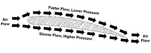
Last week we talked about Daniel Bernoulli and his famous Bernoulli Principle, which is the cornerstone of fluid dynamics. As we’ll see in this week’s installment, the Bernoulli Principle doesn’t just apply to water flowing inside pipes. Let’s consider another instance in which it is instrumental, that of an airplane wing. Figure 1 shows the side view of a wing with arrows indicating direction of air flow as the plane moves through the air. Figure 1 – A Side View of an Airplane Wing
Even though he lived more than 100 years before the first airplane, Bernoulli’s Principle can be used to explain why such a contraption can fly. You see, when comparing air flowing above and beneath a wing, its very shape makes the air flow want to travel faster along the top than it does on the bottom. Bernoulli’s principle comes into play with the airplane wing just as it did in last week’s water pipe flow example. That is, the total energy of flow is the same at all points as the air flows above and below the wing. Now, if air flow speeds up on top of the wing, then the flow’s kinetic energy increases along with it. And remember last week’s analogy of change for $100? Well, something has to give, so in this example the increase in kinetic energy is accomplished at the expense of pressure energy, but the total energy remains the same. This decrease in pressure energy then translates into a drop in pressure on top of the wing. The higher pressure beneath the wing overcomes the lower pressure above the wing. This imbalance is what provides the plane’s lift, enabling it to get off the ground once it achieves a high enough speed on its race down the runway. The Wright brothers, men ahead of their time, were actually among the first aeronautical engineers. They possessed remarkably advanced knowledge of mathematics and mechanical engineering principles. They also understood what Bernoulli taught, and they used his Principle to design and test the shapes of wings on their gliders and planes. They met with success when they determined that the wing’s shape was crucial to supplying lift. In fact, they determined that, depending on the wing’s shape, it would provide the plane with the most lift for the least amount of air speed, allowing them to use a lighter engine to drive the propellers. Weight is always a factor when flying, and the ability to use a lighter engine went a long way towards getting their first plane off the ground. That’s it for Fluid Mechanics. Next week we’ll continue with a discussion of heat transfer, which is the study of how heat moves through vacuums, gases, liquids, and solid objects. _________________________________________________________________ |
Fluid Mechanics in Mechanical Engineering, Part IV, Fluid Dynamics Continued
Sunday, January 31st, 2010|
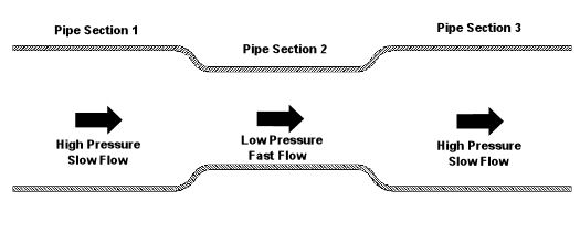
Last week we began our discussion on fluid dynamics. We saw how it’s used to determine flow and velocity of water within a pipe. This week we’ll continue our discussion, exploring in some detail the Bernoulli Principle and what it has to say on the subject. Daniel Bernoulli was a Dutch born mathematician who studied fluid dynamics during the 18th Century. He analyzed the flow of water and determined that as fluid flow speeds up, its pressure goes down, and vice versa. In 1738, he came up with what is now known as the Bernoulli Principle. This Principle is based on the First Law of Thermodynamics, which you will remember teaches us that energy cannot be created or destroyed. One of the conclusions that can be drawn from the Bernoulli Principle is that for fluid flowing steadily, say water within a pipe, or even air flowing over a pitcher’s curve ball in flight, the total energy of the flow remains constant. By “total energy,” I mean the sum of three types of energy: pressure energy, kinetic energy, and potential energy. Total energy will remain constant all along the flow, although its three parts can change. The “pressure energy” part of the total energy is due to the pressure of the fluid flow. For example, pressure energy can be added by a pump to make water flow through a pipe more readily. The “kinetic energy” part of total energy is due to the speed of the fluid flow. And as its name implies, kinetic energy is the energy of movement. The “potential energy” part of the total energy is related to a change in elevation from one end of the fluid flow to the other, like you’d have on a pipe running downhill. It can be said that water at the top of the hill has high potential energy because gravity wants to make it flow down to the bottom of the hill. So how does this Principle help us today? Well, Bernoulli’s Principle is the very foundation upon which fluid dynamics is built, and it’s consistently used to solve complex problems involving fluid flow. To illustrate Bernoulli’s Principle, let’s take a look at Figure l. Here water is flowing through a level pipe with three sections: Figure 1 – Water Flowing Through a Pipe With Three Sections
According to Bernoulli, the total energy of the flowing water is the same from one end of the pipe to the other, and the total energy is equal in each of the three sections of pipe. As the water flows through the pipe from Section 1 to the narrower Section 2, it speeds up as it squeezes through, so its kinetic energy increases. Since the total energy must remain the same and the pipe is level, (this is significant because it means that potential energy is zero), the kinetic energy increases at the expense of pressure energy. This results in a pressure drop in Section 2. Not following? Well, it’s like making change for a hundred dollar bill. Let’s say pressure energy is represented by $20 bills and kinetic energy is represented by $10 bills. Let’s also say that you have $100 worth of these bills in your wallet. The $100 represents the total energy. Now, pretend that you are water flowing into Section 1 of the pipe. While in Section 1, you look in your wallet and you find that you have four $20 bills and two $10 bills, which add up to $100. Okay. Now, when you move into Section 2, you check your wallet again. You discover that your wallet now has three $20 bills and four $10 bills. So you now have fewer $20 bills, more $10 bills, but you still have a total of $100. Fewer $20 bills means lower pressure, and more $10 bills means higher speed. Okay, getting back to the water, what do you think is going to happen when it flows from narrow Section 2 into wide Section 3? Well, the flow will slow down as it fills the extra space present in Section 3. Since the Bernoulli Principle tells us that the total energy of the flow must remain the same, the pressure energy must increase at the expense of the kinetic energy. This in turn causes the pressure within the pipe to go up and the flow’s speed to go down. Thanks to Bernoulli, if we can calculate the total energy in one section of the pipe, then we can calculate the speed of the water flow in another section if the pressure within that section is known. Again, this is possible because we know that the total energy must remain constant all along the flow. Next week we’ll see how the Bernoulli Principle applies to the other type of fluid, air. _________________________________________________________________ |
Fluid Mechanics in Mechanical Engineering, Part III, Fluid Dynamics
Sunday, January 24th, 2010|
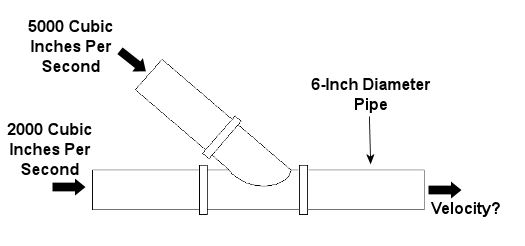
Last week, we learned about some general properties of fluids, concentrating on fluid statics, which is concerned with fluids that don’t move. This week we’ll consider a more dynamic situation, one in which the fluids do move. Remember how we talked about incompressible fluids in the first part of this series on fluid mechanics? We learned that an incompressible fluid, like the oil in a hydraulic jack, can’t be squeezed down into a smaller volume under pressure, so its volume will always remain the same. The same thing goes for other incompressible fluids, like water. By the same token, when water flows through a length of pipe, its volumetric flow rate will remain the same from beginning to end.. By “volumetric flow rate,” I mean the volume of water flowing through the pipe in a given amount of time. It’s measured in cubic inches per second (in3/sec). Now let’s revisit our discussion on the stoichiometry segment of our series on thermodynamics. It’s there that we learned that mass cannot be created or destroyed, and this concept is known as the “conservation of mass.” Applying this principle to incompressible fluids with mass, like water, we can essentially expand on that to say that volume, like mass, can’t be created or destroyed. Because of this, the volumetric flow rate entering the pipe has to equal the flow rate exiting, regardless of whether the pipe diameter changes and whether there are multiple inlets and outlets on the pipe. This volumetric flow rate is related to the velocity, or speed, of water flowing through a round pipe, as well as the interior diameter of the pipe, and it is calculated by this equation: Volumetric Flow Rate = V = (v) x (πd2/4) where “V” is the velocity of the water flowing through the pipe and “d” is the inside diameter of the pipe. The “πd2/4” part of the equation is the cross sectional area of the round pipe. This is derived from the formula used to measure the area of a circle, where the circle’s diameter is “d.” The volumetric flow rate equation above is very useful for designing piping systems used to move of fluids like water from one place to the other. For example, the equation can be used to design the piping system of a municipal water treatment plant. Waste water in, clean water out. Now let’s look at an example. Let’s consider water flowing into the pipe shown in Figure 1 below. If we know the volumetric flow rates of the water going into the two branches, then what would be the velocity of the water coming out?
Figure 1 – A Pipe With Water Flowing Through It
For this problem, let’s use the concept of conservation of volume discussed above and combine it with our volumetric flow rate equation. Applying algebra, we can use the information we are given in Figure 1 to find the solution: Volumetric Flow Rate Going In = Volumetric Flow Rate Going Out VGoing In = VGoing Out VGoing In = [(v) x (πd2/4)]Going Out (VGoing In) / (πd2/4) = vGoing Out vGoing Out = (5000 in3/sec + 2000 in3/sec) / ((π) x (6 in)2/4) = 247.6 in/sec So the water would come shooting out of the pipe at a speed of 247.6 inches per second. That’s pretty fast! Next week we’ll continue with our series on fluid mechanics and explore the Bernoulli principle. By doing so, we’ll examine what’s behind the function of airplane wings and how they enable planes to fly. _________________________________________________________________ |
Thermodynamics In Mechanical Engineering, Part I
Sunday, December 6th, 2009|
Last week we followed Dorothy through the forest and watched Scarecrow transform from a fire trap to a robust fire-retardant fiberglass composition with the help of materials science. This week we’ll explore the magical world of thermodynamics, and nobody knows thermodynamics like the Great and Powerful Oz. In fact, he’s a real “Wiz” at it! But seriously, thermodynamics is one of those out-of-sight, out-of-mind things that we take for granted in our daily lives. Without thermodynamics we wouldn’t have modern conveniences like electricity, air conditioning, or anything with a motor, like the cars we can’t seem to do without. The world would essentially be in the Dark Ages again. Often referred to as “thermo” among mechanical engineers, thermodynamics is the science that deals with heat and work in processes used in power plants, refrigeration compressors, and engines. Thermo also deals with the properties of substances that absorb and release heat energy, things like water (steam), refrigerants, and fuels (coal, gasoline, natural gas, etc.). In thermodynamics there are basically two laws that must be obeyed. The first law states that energy cannot be created or destroyed, it can only be transformed from one form into another. An example of this principle at work would be when you gas up your car. According to the first law of thermodynamics, the chemical energy that is released when gasoline is burned by the engine must add up to the work energy put out by the engine to move all its parts and accelerate the car. The first law sets up an energy accounting system, so to speak. This principle makes it possible to analyze and design engines, refrigeration equipment, etc. The second law of thermodynamics states that it is impossible to build something that is 100% efficient. So, going back to the car example above, the second law tells us that we must also account for things like the heat energy lost to the atmosphere from the hot engine parts and the fumes leaving through the exhaust pipe. This heat energy essentially wastes gasoline and doesn’t do any useful work, but it is a real phenomenon which must be dealt with when doing engineering design work. Thermodynamics can be broken down into different subsets, including power cycle analysis, refrigeration cycle analysis, stoichiometry, and psychrometrics. We’ll begin exploring these next time. _________________________________________________________________ |

