|
Imagine a chef without a fry pan, a mixer, or attempting to create a recipe without any idea of how the ingredients will combine. Is the end result likely to be something you’d want to eat? Something with just the right visual appeal, aroma, taste, and texture? Unlikely. Likewise, what good would a mechanical design be if an engineer had no idea of what kind of materials to use? The results would be haphazard, and this could lead to problems more serious than lack of palatability. We’re talking serious consequences here, such as product failure, injury, or death. In the mechanical engineering arena, just as in the cooking arena, materials used possess certain properties which render them useful for specific purposes. Just as a chef has her pantry, an engineer has a wide variety of materials available to her to choose from, and new materials are developed all the time. The vastness of the materials available to an engineer makes it difficult for all of them and their properties to be committed to memory. What is possible, however, is to develop a firm understanding of the underlying principles that govern their properties. It is this general understanding of materials’ properties that enables engineers to select between materials. There are key questions to be answered in the search for the ideal materials to do a job. Which materials would be the most economical? Which would give optimal performance? The best durability? Materials science provides an understanding of the relationship between the structure of materials at an atomic or molecular level and their macroscopic properties. In other words, the engineer learns how atoms are arranged and bonded together at a microscopic level, which in turn form the material perceived by the naked eye. The ultimate arrangement of molecules is based upon how the virgin material was processed into its final form. By “processed,” I mean the application of heat, cooling, mechanical forces, etc. Knowing the composition of a material and how it was processed allows engineers to predict how the material will react to things like stress, strain, heat, corrosives, radiation, and electrical currents. It’s a big world out there, and it’s filled with materials to explore. Next week we’ll begin that exploration. _________________________________________________________________ |
Posts Tagged ‘mechanical engineer’
Materials Science In Mechanical Engineering, Part I
Sunday, November 22nd, 2009Strengths of Materials in Mechanical Engineering
Sunday, November 15th, 2009|
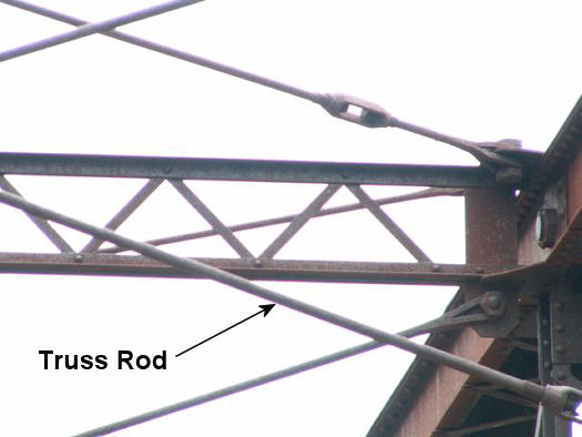
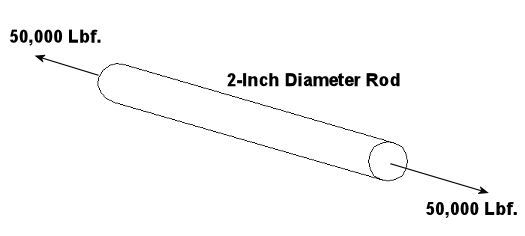
When we looked at our statics example a few posts ago, it was convenient to consider the bridge beam as being perfectly rigid. In the real world, a bridge beam is not perfectly rigid. When it’s subjected to external forces, like the weight of a truck sitting in the middle of it, there is a tendency for it to bend, deform, change its shape. If the external forces create bending and deformations that are too much for the bridge beam material to handle, it will collapse. In strengths of materials analysis, engineers must consider typical stresses that will occur within objects like bridge beams, airplane wings, bolts, and machine parts during use. Stress is a measure of force exerted per unit area of a surface. Once the stresses are known, a material is selected that is strong enough to keep the object from being bent, mashed, stretched, and/or broken. To illustrate this, let’s consider an example of a simple stress. Suppose you want to design a truss rod for a highway bridge like the one shown in Figure 1. Specifications require that the rod be two inches in diameter. Its purpose is to hold the sides of the bridge together when vehicles travel across it. Figure 1 Now suppose that the bridge is to handle traffic to and from and iron mine. Let’s consider the scenario where a truck laden with iron ore runs out of gas and comes to a stop in the middle of our bridge. Under this load, static analysis reveals that the sides of the bridge want to spread apart, putting a tension of 50,000 pounds force (Lbf.) on the truss rod as shown in Figure 2. Figure 2 Since the external force acting upon the truss rod and the diameter of the rod itself are both given, the engineer would merely have to select the appropriate material for the rod that would fall within the desired parameters, that is, so as to keep our rod from pulling apart when anticipated stressors such as a heavy truck is on the bridge. The first step would be to calculate the tensile stress within the rod itself. By tensile stress, I mean the stress in the rod due to the forces that are trying to pull it apart. In our example, this is relatively easy to assess: Stress = [Tensile Force] ÷ [Lateral Cross Sectional Area of the Rod] The lateral cross section of the rod is round, so its area would be πd2 divided by 4, where the Greek letter π (Pi) has a value of 3.1416, and d is the diameter of the rod. Therefore, the tensile stress would be: Stress = [50,000 Lbf.] ÷ [π × (2 in.)2 ÷ 4] = 15,915.49 Lbf./in.2 Knowing the stress within the rod, the engineer would next have to select an appropriate material for the rod that’s strong enough to do the job. In our case, let’s say we determine that steel is the best material to use. But what type of steel? Well, there are engineering handbooks with tables that list the mechanical properties of all sorts of materials, including metals and plastics, and along with those properties there is listed their ability to handle stress. These mechanical properties were determined in laboratory tests where carefully machined specimens of the materials were subjected to measured stresses until they deformed and broke apart. They include yield strength and ultimate strength, and these findings have been duly recorded so that future engineers need not go through independent testing of common materials themselves. Yield strength is the stress that is measured when the test specimen begins to stretch without any significant increase in force being applied to it. Ultimate strength is the maximum stress that the material in the test specimen can withstand before it starts to fail, that is tear apart, break, collapse. Our engineer would use the mechanical properties tables that are readily available to him to select the appropriate steel alloy that would meet our criteria, that is, has a listed strength high enough above the calculated 15,915.49 Lbf./in.2 tensile stress to provide a sufficient factor of safety. Factors of safety are listed in engineering books for yield strength and ultimate strength and they are selected depending on how the forces are applied to a structural component or machine part (e.g. steady, varying, or shock). When strengths of materials analysis involves the solution of complex statics and dynamics problems, things become a little less straightforward. And when you are dealing with components having odd shapes and a combination of stresses, say due to compression and torsion, things become even more complex. In any case, engineers must have extensive knowledge of the properties of materials in order to anticipate factors at play in real world scenarios such as the one we’ve been discussing. Ever wonder why some steel is hard and brittle, and some is soft and bendable? Well, our next topic of discussion will be about materials science, the study of how metal alloys and polymers are formed to have specific properties. _________________________________________________________________ |
Kinematics of Machines in Mechanical Engineering
Sunday, November 8th, 2009|
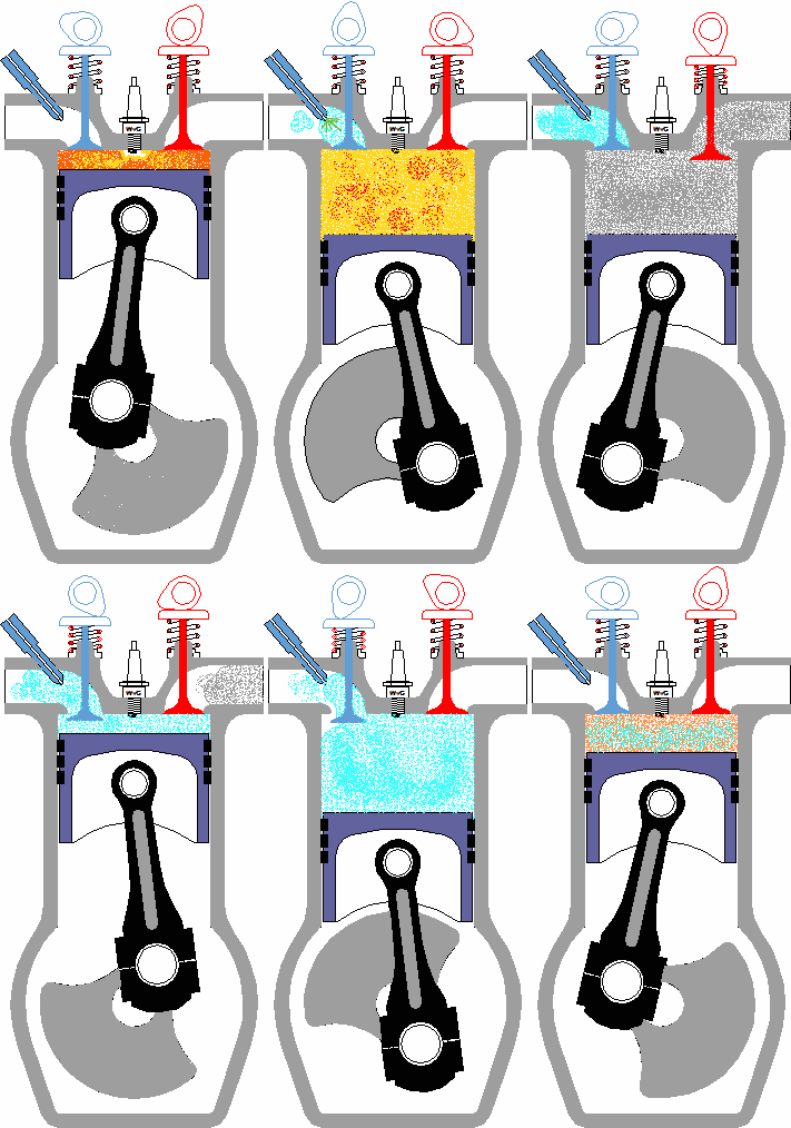
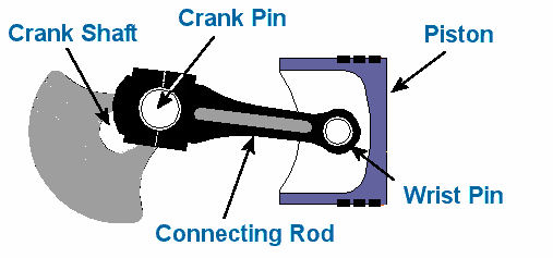
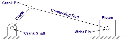
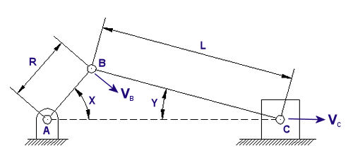
When we refer to the study of the kinematics of machines, we’re referring to the relationship between machine parts and how those parts behave as they move through their ranges of motion. What this means is that there is particular concern with the relative motion of machine parts, that is, how they relate to each other, their position, distance, velocity, and acceleration. When speaking of the kinematics of machines, a mechanism is considered to be like a chain with a system of links that are connected together. This chain is constrained, meaning that independent movement of one part is not possible. These parts are interconnected, and they all move relative to each other. Motion in any one link of this kinematic chain will result in a relative and predictable motion to each of the others. Now, by “chain,” I don’t necessarily mean a chain in the physical sense, but rather the fact that the parts of the mechanism are linked together. To illustrate what I’m talking about, let’s consider the gasoline engine shown in Figure 1 below. Figure 1 To help you follow along, let’s turn the engine on its side and name the parts of one of its kinematic chains. This is shown in Figure 2. Figure 2 Suppose you want to analyze how fast the engine’s piston is moving at any given instant during its operation. Suppose further that you know how fast the crank shaft is turning. Where would your analysis begin? Well, while studying the motions of machine parts, it’s helpful to draw the parts first in skeletal form so that only those dimensions that affect their motions are considered. Let’s represent the kinematic chain of Figure 2 in skeletal form. See Figure 3 Figure 3 Lastly, we embellish the skeleton with the depiction of angles that are at play as the parts of our engine move, and we add the relevant symbols that will allow us to build the equations we’ll be working with. This is shown in Figure 4. Figure 4 So, as the engine runs, the crank AB rotates around the center of the crank shaft A. The connecting rod BC is attached to the piston at the wrist pin C. The piston moves back and forth as AB rotates. Now here is where things get a little hairy, and for some of you it may look somewhat like code or a foreign language. The tangential velocity VB of the crank pin B is shown in Figure 4 as a vector. A vector is something which depicts both a magnitude and direction. And since VB is a “tangential velocity,” it is moving in a direction which is at a right angle, that is, at a 90-degree angle in relation to the crank AB. This relationship will always exist between VB and the crank AB. In the posed scenario, VB is a velocity, so let’s say its magnitude will be in units of inches per second. The magnitude of the vector VB is then directly related to the speed of crank shaft AB and is determined by this equation: VB = 2∏RN ÷ 60 Referring to Figure 4, R is the distance between the center of the crank shaft and the center of the crank pin in inches. N is the rotational speed of crank AB in revolutions per minute (rpm). If one knows the crank angle X, the crank length R, and the connecting rod length L in Figure 4, they can then use trigonometry to determine the velocity of the piston. This velocity is represented by the vector VC, and its magnitude, or value, would be found by using the following equation… VC = [VB] × [sin(X + Y)] ÷ [sin(90° – Y)] …where the angle Y is found by: Y = [sin-1(R ÷ L)] × [sin(X)] Analysis of kinematics of machines would become even more complicated when complex mechanisms like oddly shaped linkages, cams and followers, and gear trains are involved. Our next mechanical engineering topic will be: Strength of materials, the study of the properties of materials. Geometry and sizing of structural components, structures, and machine parts will also be explored. _________________________________________________________________ |
Mechanical Engineering, Focus on Dynamics, Part II, Kinetics
Monday, November 2nd, 2009|
In Part I of Mechanical Engineering, Focus On Dynamics, we talked about kinematics. This week in Part II, we’ll talk about kinetics. Kinetics is the study of the relationship that exists between forces acting on a body, the mass of the body itself, and its motion. It’s used to predict the motion caused by given forces acting on a body or to determine the forces required to produce a motion of the body. In kinetics forces can be attributed to the motion of an object by way of Sir Isaac Newton’s Second Law of Motion. In other words, this law relates the kinematics of an object to the forces applied to it, and in equation form that relationship looks like this: Force = [Mass] x [Acceleration] “Mass” is the weight of the object, in pounds, divided by the acceleration of the Earth’s gravity. On Earth, the acceleration of gravity is considered to be a constant and is taken to be 32.2 feet per second, per second. (No, that’s not a typo.) Legend has it that Newton discovered the earth’s acceleration when gravity caused an apple to fall from a tree and hit him on the head. That may or may not be true, but Newton’s Second Law of Motion forms the foundation for the study of kinetics. To illustrate how kinetics works, we can look at another very simple example. Suppose you have a block of steel that weighs 50 pounds, and it is sitting still on a nice smooth, frictionless sheet of ice (see Figure 1). Figure 1
How hard would you have to push on the side of this block to make it accelerate across the ice at a rate of 10 feet per second, per second? Use Newton’s second law to find out: Force = [(50 Lb.) ÷ (32.2 ft./second2)] x [10 ft./second2] Force = 15.5 Lb. Force and energy calculations in kinetics can get really complicated, especially when you have to consider the effects of friction, forces acting at angles, velocity, rotation, motion constraints, collisions, etc. Our next mechanical engineering topic will be: Kinematics of Machines, the study of how parts of machines behave as they move through their ranges of motion. _________________________________________________________________ |
Mechanical Engineering, Focus on Statics
Sunday, October 18th, 2009|
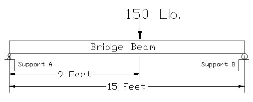
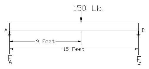
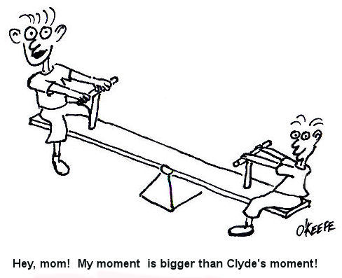
As I stated in my last blog post, Statics is the study of how forces are transmitted to and throughout stationary objects. Let’s learn a little bit about how statics is used by mechanical engineers to solve problems. Consider a perfectly rigid bridge beam sitting on two supports (see Figure 1). Now suppose you decide to stand on it. The weight of your body would push down on the beam, creating a system of forces that act upon the beam. If the beam stays on its supports and doesn’t move (it remains static), then the forces are said to be in “equilibrium.” In other words, since the beam doesn’t move when you stand on it, the sum of all the forces acting upon it are zero. Figure 1 So what, you say? Well, this concept of forces in equilibrium helps mechanical engineers analyze external and internal forces acting on stationary objects that have importance to us in real life, like bridges, machines, traffic signal masts, etc. This analysis is used to calculate the magnitudes of all the forces acting on these objects so they can design parts of the objects to be strong enough not to break apart. Think about that next time you get ready to cross a bridge in your car. To show how this works, consider the bridge beam scenario I discussed above. Suppose you weigh 150 pounds and you stand nine feet from the left end of the bridge beam (see Figure 2). Your weight will exert a downward force of 150 pounds upon the beam (let’s ignore the weight of the beam in this case). The weight of your body creates reaction forces on the beam at Support A and Support B. To consider these reaction forces, the mechanical engineer would draw what is called a “free body diagram” (see Figure 3). Figure 2 Figure 3 The reaction forces (FA and FB) at the supports A and B push up on the bottom of the beam. If the beam remains static, then the sum of the reaction forces will equal the 150 pound weight force from your body. That is, the reaction forces cancel out the 150 pound force if the beam doesn’t move and they are said to be in equilibrium. But in our example above, you’re not standing in the exact center of the beam, hence the two reaction forces are not going to be equal. More of your body weight force is bearing down on Support B and less on Support A. So how do you determine the values of the reaction forces in a situation like this? You consider “moments.” A moment is mechanical engineering lingo for a force multiplied by a distance. Moments want to rotate objects. This is an important concept in statics because if an object doesn’t move, it certainly won’t rotate, so the sum of all the moments acting on the object are zero. So, in the case of our bridge beam, the sum of the moments acting on Support A would be zero, or mathematically speaking: Sum MA = [(FA) x (0 Feet)] – [(150 Lb.) x (9 Feet)] + [(FB) x (15 Feet)] = 0 Using algebra, you can find the value for the reaction force at Support B: [0] – [(150 Lb.) x (9 Feet)] + [(FB) x (15 Feet)] = 0 [(FB) x (15 Feet)] = [(150 Lb.) x (9 Feet)] FB = 90 Lb. So what about the reaction force at Support A? If you remember, I said that if the bridge beam remains static, then the sum of all the forces acting on it will be zero. Knowing that, you can use algebra to solve for the reaction force at Support A: FA -150 Lb + FB = 0
FA = 150 Lb. – 90 Lb. = 60 Lb. So that is the basic concept of statics. Remember, in statics, nothing moves, so mechanical engineers use that to their advantage when they analyze forces acting on objects. Our next topic will be: Dynamics, the study of the effects of velocity and acceleration and resulting forces and the energy of moving objects. Last week’s Riddle: Everyone knows us to be racing by when they look at a clock, but mechanical engineers also know us to add up to zero when they look at a fixed structure. What are we? Answer: Moments _________________________________________________________________ |
Mechanical Engineering, Not Just About Gears
Sunday, October 11th, 2009|
When I was a kid I had a friend who thought that everyone who said they were an engineer wore pinstriped bib overalls and drove trains. Funny thing is, I later became both a locomotive engineer and a degreed mechanical engineer, but that’s a story for another time. Speaking of engineers, what do you think of when you hear the words, “mechanical engineer?” If you’re like most, you probably think of someone who designs gears and machinery. But the field of mechanical engineering is far more complex than that. Mechanical engineering is one of the oldest and broadest of engineering disciplines. It encompasses a broad number of disciplines, from physics to materials science, but it can be summarized as being derived from ten core areas:
Armed with this knowledge, mechanical engineers can take on design projects ranging from airplane propellers to utility power plants. During the coming weeks we will focus on each of these areas and explore them more fully. We may even have a little quiz at the end to test your newfound knowledge! Our first topic will be: Statics, the study of how forces are transmitted to and throughout stationary objects. And here is a riddle to get you started in your personal exploration of the subject matter: Everyone knows us when they look at a clock, but mechanical engineers also know us to add up to zero when they look at a fixed structure. What are we? Get the answer in my next blog post. _________________________________________________________________ |

