|
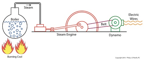
In my work as an engineering expert I’ve dealt with all forms of energy, just as we’ve watched James Prescott Joule do. He constructed his Joule Apparatus specifically to demonstrate the connection between different forms of energy. Today we’ll see how he furthered his discoveries by building a prototype power plant capable of producing electricity, a device which came to be known as Joule’s Experiment With Electricity. Joule’s Experiment With Electricity As the son of a wealthy brewer, Joule had been fascinated by electricity and the possibility of using it to power his family’s brewery and thereby boost production. To explore the possibilities, he went beyond the Apparatus he had built earlier and built a device which utilized electricity to power its components. The setup for Joule’s experiment with electricity is shown here. Coal was used to bring water inside a boiler to boiling point, which produced steam. The steam’s heat energy then flowed to a steam engine, which in turn spun a dynamo, a type of electrical generator. Tracing the device’s energy conversions back to their roots, we see that chemical energy contained within coal was converted into heat energy when the coal was burned. Heat energy from the burning coal caused the water inside the boiler to rise, producing steam. The steam, which contained abundant amounts of heat energy, was supplied to a steam engine, which then converted the steam’s heat energy into mechanical energy to set the engine’s parts into motion. The engine’s moving parts were coupled to a dynamo by a drive belt, which in turn caused the dynamo to spin. Next time we’ll take a look inside the dynamo and see how it created electricity and led to another of Joule’s discoveries being named after him. Copyright 2015 – Philip J. O’Keefe, PE Engineering Expert Witness Blog ____________________________________ |
Posts Tagged ‘mechanical engineering expert witness’
Joule’s Experiment With Electricity
Friday, October 16th, 2015Calculating Velocity — de Coriolis’ Kinetic Energy Formula
Monday, September 28th, 2015|
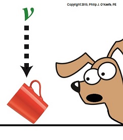
Last time we introduced Gaspard-Gustave de Coriolis’ formula to compute kinetic energy. Today we’ll use it to determine the speed of descent, or velocity, of the coffee mug we’ve been watching closely in the last few blogs. To calculate the mug’s velocity, we must bear in mind physicist Julius Robert von Mayer’s assertion that all forms of energy are interrelated, and in fact interchangeable, because energy can neither be created nor destroyed, it can only change forms. For a refresher, see The Law of Conservation of Energy. Let’s now put a practical spin on this concept and apply it to our coffee mug’s free fall to the floor. Once again, de Coriolis’ formula, KE = ½ × m × v2 (1) where m is the mass of our falling object and v its velocity. The ½ is an unchanging, constant term that’s present due to the mathematical Rules of Integration governing integral calculus. Calculus and its derivations are beyond the scope of this blog, but if you’re interested in pursuing this, follow this link to, The Physics Hypertextbook – Kinetic Energy. According to von Mayer’s Law, at the precise instant before the mug hits the floor its kinetic energy, KE, is equal to the potential energy, PE, it possessed when it rested passively on the shelf. Stated another way, the instant before the mug makes contact with the floor, all its potential energy will have been converted into kinetic. The mug’s PE was calculated previously to be equal to 4.9 kg • meter2/second2. See Computing Potential Energy for a review. Knowing this, the mathematical relationship between the mug’s potential and kinetic energies is expressed as, PE = KE = 4.9 kg • meter2/second2 (2) By substituting this mathematical representation for KE into equation (1) we arrive at, 4.9 kg • meter2/second2 = ½ × m × v2 (3) We also know the mug’s mass, m, to be equal to 2.6 kilograms, so integrating that into the right side of equation (3) it becomes, 4.9 kg • meter2/second2 = ½ × ( 0.25kg) × v2 (4) That leaves the mug’s velocity, v2, as the only remaining unknown term. We’ll use algebra to isolate this variable by dividing both sides of equation (4) by ½ × ( 0.25kg). (4.9 kg • meter2/second2) ÷ [½ × ( 0.25kg)] = v2 39.20 meter2/second2 = v2 Finally, we’ll take the square root of the equation to place it in terms of v. 6.26 meters/second = v The mug’s velocity an instant before impact equates to 6.26 meters/second, or almost 21 feet per second. Next time we’ll discuss a metric unit used to measure energy known as the Joule and discover the man behind it. Copyright 2015 – Philip J. O’Keefe, PE Engineering Expert Witness Blog ____________________________________ |
Willem Gravesande’s Experimentation on Kinetic Energy
Friday, September 11th, 2015|
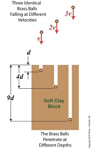
Last time we introduced The Law of Conservation of Energy, which holds that energy can neither be created nor destroyed. We then applied the concept to a mug resting on a shelf, brimming with latent gravitational potential energy. Today we’ll continue our discussion with a focus on kinetic energy and how Willem Gravesande’s experimentation contributed to our understanding of the subject. The concept of kinetic energy was first posited by mathematicians Gottfried Leibniz and Johann Bernoulli in the early 18th Century when they theorized that the energy of a moving object is a factor of its mass and speed. Their theory was later proven by Willem Gravesande, a Dutch lawyer, philosopher, and scientist. Gravesande conducted experiments in which he dropped identical brass balls into a soft clay block. See Figure 1. Figure 1 Figure 1 shows the results obtained when balls of the same mass m are dropped from various heights, resulting in different velocities as they fall and different clay penetrations. The ball on the left falls at velocity v and penetrates to a depth d. The center ball falls at twice the left ball’s velocity, or 2v, and penetrates four times as deep, or 4d. The right ball falls at three times the left ball’s velocity, 3v, and it penetrates nine times deeper, 9d. The results indicate an exponential increase in clay penetration, dependent on the balls’ speed of travel. In fact, all the kinetic energy that the balls exhibited during freefall was converted into mechanical energy from the instant they impacted the clay until their movement within it stopped. This change in forms of energy from kinetic to mechanical demonstrates what Julius Robert von Mayer had in mind when he derived his Law of Conservation of Energy. For a refresher on the subject, see last week’s blog, The Law of Conservation of Energy. As a result of his experimentation, Gravesande was able to conclude that the kinetic energy of all falling objects is a factor of their mass multiplied by their velocity squared, or m × v2. We’ll see next time how Gravesande’s work paved the way for later scientists to devise the actual formula used to calculate kinetic energy and then we’ll apply it all to our coffee mug falling from the shelf. Copyright 2015 – Philip J. O’Keefe, PE Engineering Expert Witness Blog ____________________________________
|
Centripetal Force
Friday, July 3rd, 2015|
Have you ever wondered how Earth keeps its steady orbit around its life sustaining sun, or what prevents it from breaking away and flying off willy-nilly into the universe? It’s more than just simple gravity, it’s the physics behind centripetal force, the topic we’ll be exploring today. We’ve been working our way towards a full discussion on gravity in this long blog series, navigating subjects such as the behavior of falling objects, the acceleration of gravity, the masses of Earth and the sun, and the optical measurement of cosmic distances. We’ve now come full circle from my opening blog on the subject, Gravity and the Mass of the Sun. In that blog an equation was introduced as a means to calculate the mass of the sun, and in that equation is the variable we’ll be working towards solving today, Fg, the sun’s gravitational force upon the Earth. Here again is that equation, M = (Fg × r2) ÷ (m × G) Gravity, mass, and distance all come into play in forming the structure of our universe, and the variables in this equation reflect that: M, the mass of the sun, r the distance between Earth and the sun, m the Earth’s mass, and G the universal gravitational constant. With the exception of Fg, all variables in this equation have already been solved for in previous blogs in this series. For a refresher go to, Calculating the Distance to the Sun, What is Earth’s Mass? and Newton’s Law of Gravitation and the Universal Gravitational Constant. As there is no direct means to measure the cosmic quantity, Fg, we’re left to an indirect method for its computation. The indirect method is based on the phenomenon of centripetal force, Fc something most children become acquainted with when they experience the thrill of twirling an object attached to a string, say a rubber ball, above their heads. See Figure 1. Figure 1 As the ball is twirled, the string becomes taut. The energy exerted upon it by the child’s hand, coupled with the ball’s mass and traveling speed/velocity, v, make the ball want to move off in a straight trajectory into space, like a launched projectile. But the string it’s attached to prevents it from doing so, forcing the ball to instead travel a circular path around the center point of rotation. The taut string and the ball’s circular path are evidence of centripetal force, Fc, at work. Next time we’ll employ Isaac Newton’s Second Law of Motion to the centripetal force phenomenon to see how the sun’s gravitational force keeps Earth in a stable circular orbit around the sun.
____________________________________
|
The Transit of Venus
Monday, May 18th, 2015|
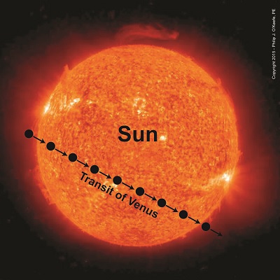
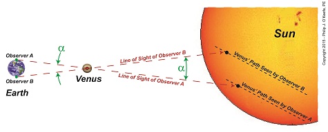
Last time we learned of Johannes Kepler’s Third Law of Planetary Motion and his development of the astronomical unit (AU) and how these contributed to bringing ancient scientists a step closer to calculating Earth’s distance to the sun. Today we’ll see why Kepler’s focus on Venus, specifically its travel through space in relation to Earth and the sun — the so-called transit of Venus — would become the crucial element to solving the puzzle. Astronomers had previously used the Earth itself as an optical rangefinder to calculate distance to the moon. But unlike the moon which is relatively close to Earth, the sun is many tens of millions of miles away, too distant to be used in that manner. When it came to finding the distance from Earth to its sun, they were stumped. Then in 1716 Edmund Halley had the insight to combine Kepler’s Third Law and the parallax principle with Venus’ orbital journeys to devise an ingenious solution to the problem. The transit of Venus, first predicted by Kepler in 1627, is a rare astronomical phenomenon which only occurs every 243 years. At this time Venus becomes clearly visible from Earth and appears as a black dot traveling a straight path across the fiery backdrop of the sun’s surface. Figure 1 shows this phenomenon as it would look from Earth. According to Halley’s plan, two observers with telescopes would be positioned on opposite sides of the Earth. Due to the principle of parallax their lines of sight would provide different perspectives of Venus’ path. See Figure 2. From the perspective of Observer B, Venus’s path would appear higher on the sun’s face than the path seen from the perspective of Observer A. As their lines of sight converge on Venus’ center, an angle forms between them, which we’ll name α. The same angle forms as they look past Venus to the sun in its backdrop. Halley theorized that if the angle α could be measured, Kepler’s Third Law could be used together with trigonometry to calculate the distance between Earth and the sun, Kepler’s so-called AU. We’ll review Halley’s methodology next time.
____________________________________
|
Optically Measuring Cosmic Distances
Wednesday, April 22nd, 2015|
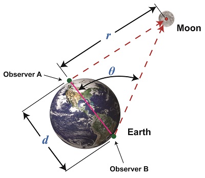
Last time we learned that the bigger an optical rangefinder, the better its accuracy in measuring distant objects. Today we’ll take that concept a step further when we discover how Earth itself was used by ancient scientists to gauge its distance to the moon. Today’s blog will be strewn with embedded links to past blogs in this series, all of which have been building up to our understanding of gravity, a complex subject with many pieces to its puzzle. There are a few remaining pieces to be placed which will be covered in future blogs, but I promise we’ll get there. Long before Edmund Halley’s time, scientists used the Earth as a huge optical rangefinder. In doing so they employed the principles of parallax and trigonometry to obtain reasonably accurate measurements of the distance between Earth and its nearest neighbors, starting with the moon. See Figure 1. The illustration shows how it was done. Two observers armed with telescopes viewed the moon from opposite sides of the earth. Their lines of sight are represented by dashed lines, and together with the solid pink line which represents the distance between them, d, a right triangle was formed. Because Observer B was situated on the other side of the globe, his line of sight fell at an angle relative to Observer A’s, due to the Principle of Parallax. The angle that formed at the point in the triangle at which B was situated we’ll call θ. The fact that a right triangle was formed at Observer A’s observation point will enable our ancient scientists to use principles of trigonometry and parallax in their quest to find the distance to the moon. Follow this link to a refresher blog on the subject, Using Parallax to Measure Distance. At precisely the same moment the moon moved into Observer A’s telescopic line of sight, Observer B adjusted his telescope to center the moon within it. Observer B then duly measured the angle θ formed with a protractor, just as would be done with a rangefinder. If you’ve been reading along in this series, this setup might look familiar to you. In fact, the two mirrors of a military optical rangefinder work in exactly the same way as our two observers looking at the moon. Follow this link to a refresher on the internal workings of a rangefinder. Once the angle θ’s value had been determined, it was used to calculate the distance r between Earth and the moon with the same equation we’ve been using to measure distances using military optical rangefinders: r = d × tan(θ) As far as our moon observers go, the only variable left for them to determine before they are able to measure Earth’s distance to the moon is d, the distance between their viewing positions on Earth. We’ll see how to solve for d next time, when we put the Earth’s geometry to work for us.
____________________________________
|
Optical Rangefinders, Bigger is More Accurate
Tuesday, April 14th, 2015|
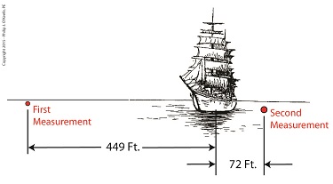
Last time we touched on the fact that bigger is better when it comes to using a rangefinder to measure extremely long distances. Today we’ll expand on that theme and discover how bigger is indeed more accurate. Returning to our previous example, we’re still trying to find the distance to that ship on the horizon. We’ve got two rangefinders at our disposal, one short, one long, and the measurements provided by them are vastly different. Which is correct? To find out, we’ll hypothesize that we’ve taken the time to meticulously measure the distance the hard way, with a really long tape measure. Doing so, we find the actual distance to the ship is 5280 feet. We can now compare the actual measured distance to the measurements taken with our two rangefinders and compare their accuracy: Rangefinder One = 5729 feet – 5280 feet = 449 feet Rangefinder Two = 5208 feet – 5280 feet = -72 feet The smaller rangefinder results in a difference, or error, of 449 feet, while the bigger results in a difference of 72 feet. It’s clear that the bigger rangefinder gets us closer to the actual measurement taken by tape measure, so it’s the most accurate. The obvious conclusion is that the bigger the rangefinder used, the smaller the error factor. That’s because as the length of the rangefinder increases, the smaller the angle θ becomes, a situation which results in the tangent of θ moving farther away from rather than closer to 90°, all of which translates to more accuracy in our rangefinder’s measurements. Put another way, the bigger the rangefinder, the less likelihood there is of its angle θ‘s tangent hovering near 90° and becoming asymptotic, an undesirable outcome for reasons explained in a previous blog in this series. Next time we’ll see how early astronomers were able to arrive at relatively accurate calculations of the distances between Earth and other heavenly bodies by using the parallax effect produced by the world’s largest optical rangefinder, Planet Earth itself. ____________________________________
|
Further Limitations of an Optical Rangefinder
Monday, March 30th, 2015|
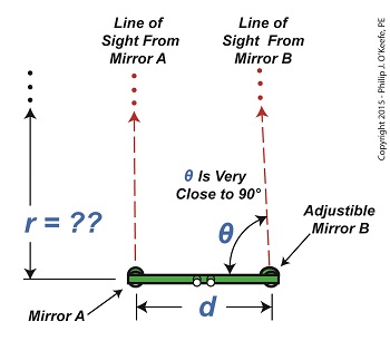
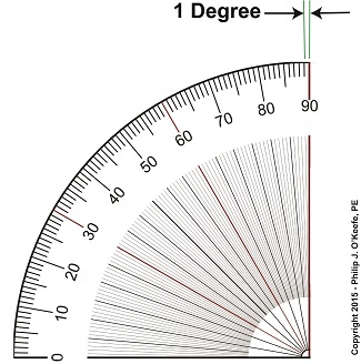
Last time we discovered that when optical rangefinders are used to measure the distance to objects extremely far away we encounter problems. We discussed one of them last time, the fact that as θ approaches 90° the tangent of θ becomes asymptotic, resulting in a situation where even the most minute changes to θ bring about huge corresponding changes to the distance, r, we seek to measure. This difficulty goes hand in hand with another we’ll be discussing today, the problem of very tight spaces. They both lead to a greater potential for measurement inaccuracies. The rangefinder in Figure 1 depicts the kind of situation that often results when attempting to measure objects that are extremely far away, like a ship on a distant horizon. Angle θ is very close to being 90°. Let’s see what that does to our measuring attempts with the rangefinder’s on-board measuring scale, its indicator gauge. The fact is, when a rangefinder’s indicator gauge hovers near 90°, it becomes user unfriendly. To illustrate, let’s refer to a common everyday protractor, shown in Figure 2. Protractors are divided into 1° gradations, which allow us to measure angles between 0° and 90°. This interval is fine for many angle measuring purposes, but we’ll see in a moment why it doesn’t work when measuring extremely long distances. A similar protractor is found on a rangefinder’s indicator gauge, enabling us to measure the angle θ. Notice how small the space is between 89 and 90 degrees. Now imagine having to split that area into hundreds, even thousands, more gradations in order to accurately assess the value of θ. This is precisely the situation we encounter when using a rangefinder to measure extremely long distances where the lines of sight form long, narrow triangles and θ hovers near 90°. Are you beginning to see — or rather not see — the problem? When this situation exists, ultra fine gradations must be made between the 89th and 90th degrees in order to make an accurate measurement of θ . This results in a situation where gradation marks are spaced so closely together they become difficult, if not impossible, for the unaided human eye to read. Next time we’ll see why bigger is indeed better when seeking to solve this problem. ____________________________________
|
Limitations of an Optical Rangefinder
Monday, March 23rd, 2015|
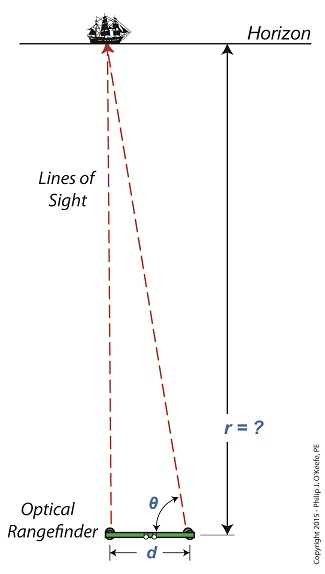
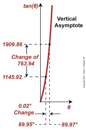
Last time we touched on the limitations of optical rangefinders when attempting to measure extremely long distances. Today we’ll expand on that theme. Let’s say we want to use a rangefinder to determine the distance, r, to an object that’s extremely far away, like a ship on a distant horizon, as shown in Figure 1. Figure 1 It’s obvious that the rangefinder’s length, d, is extremely small in comparison to the total distance viewed, r. When this situation exists, a very long and narrow right triangle is formed between the lines of sight provided by mirrors A and B of the rangefinder, represented by two red dashed lines, and the length of the rangefinder itself, d. It’s still a right triangle, a necessary condition to using our rangefinder formula to determine distance, however, when the triangle is an extremely long, narrow one, the angle θ approaches 90° in value. As discussed in a previous article, a θ value of 90° is impossible for the rangefinder distance formula to work with. The more distant the ship, the longer and narrower the triangle becomes, causing θ to creep ever closer to 90°. From a trigonometric point of view, this spells trouble. The problem is, the closer θ gets to 90°, the greater the disparity potential in its measurement. For example, let’s suppose that when the ship is first sighted with the rangefinder θ is measured at 89.95°. Then a second later the same person seeks to verify his measurement. Without noticing that he’s doing it, he shifts weight on his foot ever so slightly, takes a second reading, and finds that this time θ is 89.97°. That’s a difference of only 0.02° between readings, but it produces a huge change in the tan(θ). Figure 2 represents a graph of these two measurements, with the angle θ values on one axis, the tan(θ) values on the other. Figure 2 The graph illustrates how this minute change in θ of only two hundredths of a degree (0.02°) results in a correspondingly huge change to tan(θ) of 763.94 units. We know that the rangefinder’s length, d, equals 3 feet, so plugging all the numbers into our rangefinder formula we determine the distance to the ship to be, r = d × tan(θ) r = 3 feet × 763.94 = 2291.82 feet What this means on a practical usability level is that when the rangefinder’s adjustable mirror B moves only two one hundredths of a degree, it results in a change to the distance viewed, r, of almost half a mile! There’s another problem that goes hand in hand with the one presented today. We’ll explore it next time.
____________________________________
|
Tangent and the Vertical Asymptote
Monday, March 2nd, 2015|
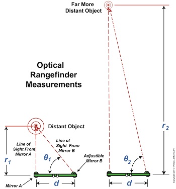
Imagine working, working, working towards a goal and getting oh so close, but never being able to actually reach it. It’s happened to all of us some of the time, but with vertical asymptotes it happens all of the time. We’ll see why the nature of vertical asymptotes presents a problem when measuring extreme distances in today’s blog. We’ve found that optical rangefinders can be useful in measuring long distances. They work well in many situations, but not all. When it comes to extremely long distances they aren’t at all helpful. That’s due to problems presented by trigonometry, more specifically the tangent function and how it leads to vertical asymptotes. Let’s look at Figure 1 to bear this out. Figure 1
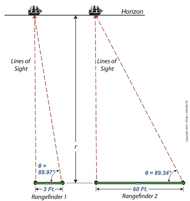
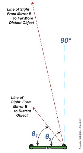
In Figure 1 we see the same rangefinder being used to view objects at two different distances, one distance far greater than the other. There’s an obvious difference in the lengths of the sides of the triangles formed, as well as an obvious difference in angles θ1 and θ2. θ2 is much steeper than θ1. This is more apparent when the lines of sight are isolated, as shown in Figure 2. Figure 2
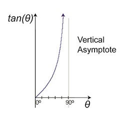
Figure 2 shows that as an object becomes more distant and r, the distance to the object viewed increases, the angle θ gets closer and closer to a value of 90°. What’s significant about this is that a θ value of 90° is impossible for a rangefinder to work with. Why? Because it uses trigonometry to measure distances, more specifically the tangent function within trigonometry, and when θ takes on a value of 90°, it becomes asymptotic in nature — a situation which renders the optical rangefinder useless. To visualize this, we’ve plotted the tangent function for an array of angle θ values on a graph in Figure 3. Figure 3
The curved line represents plotted tangent values for θ that fall between 0° and 90°. What it demonstrates is that as θ gets closer to becoming 90°, it becomes more vertical and steeper in incline. In other words, it forms a vertical asymptote, stretching to reach a value of 90° but never actually getting there. In the math world this means that the tangent’s value is on its way to becoming unbounded or undefined. In plain English this means that the tangent’s value becomes increasingly more unworkable. In fact, the tangent of 90° degrees does not exist. Try entering the number 90 into your calculator and pressing the TAN button. You’ll receive an error message in return. Next week we’ll see the impact this has on the function of an optical rangefinder when the object viewed is so far away the angle θ approaches a value of 90°.
____________________________________
|
