| Last week I said we’d talk about ground fault circuit interrupters (GFCI), but before we get to that let me provide a little background on how I recently came to be a subject matter expert for The Discovery Channel.
The program I was asked to contribute to is titled, “Curious and Unusual Deaths,” where I will be discussing a variety of tragic occurrences, including deaths by electrocution. It’s actually slotted to be a series of half-hour segments presenting, you got it, some of the strangest, most grizzly, tragic, or simply avoidable deaths from across the globe and throughout time. The episodes use actors to recreate the incidents, which take place in a variety of locations, from the home to the workplace. After presenting a graphic portrayal of the unfortunate event, experts, including myself, provide an explanation of the science behind it all. Cinematic recreations and high quality computer generated imagery are used to recreate how the deaths occurred as well as illustrate the experts’ explanations. It all started when I was contacted by a researcher for the program. She had discovered me through this very blog site, the Engineering Expert Witness Blog, and was impressed with my diverse background, which as my loyal readers know covers both mechanical and electrical engineering. She also liked the fact that I’ve worked professionally within many different industries. Needless to say, I was flattered. She went on to explain that she was interested in discussing with me the technical aspects of four particularly unusual but actual incidents that had proven to be deadly to those involved in them. The deaths were due to a variety of factors, from a steam pipe failure, to contacting high voltage electronics through a seemingly benign unplugged appliance, to succumbing to carbon monoxide poisoning produced by a propane heater, and finally, the one I thought to be most unusual of all, a death caused by touching a hotel room door that was, unbeknownst to the person inserting the key in the lock, charged with stray electrical current from an unlikely source. Sound interesting? Look for the series to air in the near future to find out more. We discussed the incidents by phone for awhile, and then a week later I received another call inviting me to fly up to Toronto, Canada, to be videotaped as an expert for the series. Now, although I do not have a ham bone in my body, I do enjoy sharing my knowledge of technical things with others, so I gladly took her up on the offer. Tune in next week to read the insider’s track on the making of a quality television series. _____________________________________________ |
Posts Tagged ‘mechanical engineering’
Just Call Me Expert
Sunday, June 12th, 2011Machine Design in Mechanical Engineering
Sunday, March 21st, 2010|
Last week we wrapped up our discussion of vibration analysis. It’s been a long time coming, but this week we’ll conclude our series on the many aspects of mechanical engineering by discussing machine design. If you’ve been with us since the beginning of the series and you’re not a mechanical engineer, I’d venture to say you’re now impressed with the wide scope of issues with which mechanical engineering is concerned. In our preceding discussions we examined some basic concepts behind statics, dynamics, kinematics, strengths of materials, material science, thermodynamics, heat transfer, fluid mechanics, and vibrations. This is the foundation of mechanical engineering know-how. But when we consider machine design as a whole, we often have to keep in mind the old cliché, “Why reinvent the wheel?” I say this because engineers have been designing machines and mechanical systems for hundreds of years. Over this time, their design accomplishments have been collected, standardized, and tabulated in engineering handbooks and product catalogs to make things easier for future generations and to eliminate redundancy of work effort. Put another way, why design nuts, bolts, pumps, heat exchangers, motors, gears, pulleys, and drive belts for a new machine when someone already designed them for similar applications in the past and they are readily available for quick purchase from suppliers? For example, suppose you had to design a machine that will be driven by an electric motor using sprockets and a roller chain. This is the same method that your bicycle employs to transfer foot power applied to the pedals back to the rear wheel, which gets you rolling. So, how do you come up with a chain that will do the job without breaking? To incorporate a sprocket and roller chain drive system into your machine design, you must first determine how much horsepower you will need to run the machine, the speed at which it must operate, and the conditions under which it will operate. You can use this information to design a chain from scratch, then test it to see if it works, then have it custom manufactured. Translation: Lots of time, effort and money expended. Or, you could get a hold of a book that’s been around since 1914, Machinery’s Handbook. This is considered by many to be one of the best mechanical engineering reference handbooks of all time. It contains tables of information that can be used to select standard, commercially available roller chains based on both horsepower and speed requirements. It also has lots of other engineering-specific information on various other machine components. Based on our example above, I think you can conclude that the fastest, most economical route to take to construction of our mechanism is to use as many standardized, commercially available components as possible. Knowing where to find information on these components and how to use them is very important to the success of your design, and this is precisely the information that you would have picked up during your final year of study towards earning a Bachelor’s Degree in Mechanical Engineering. As a student, you would have been required to take at least a few machine design courses. Well, that’s it for our series on understanding the basics of mechanical engineering. I hope you enjoyed it and it helped you to better understand the fundamentals of what mechanical engineering is all about. _________________________________________________________________
|
Vibration Analysis in Mechanical Engineering, Part II
Sunday, March 14th, 2010Vibration Analysis in Mechanical Engineering, Part I
Sunday, March 7th, 2010|
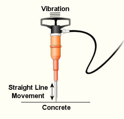
Last week we wrapped up our discussion on heat transfer. This week we’ll turn to a discussion on vibration analysis. Vibration occurs when there is physical movement of a machine part when compared to a point of reference. This physical movement can manifest in a straight line, a circle, or any way imaginable in three dimensions. The point of reference can be a guideway for a sliding part or a shaft for a rotating part. As discussed in kinetics, machine parts have mass, and when mass moves it contains kinetic energy, so it makes sense that when a part moves within a machine, the energy created can result in forces that act upon the machine as a whole. The net result is machine vibration which occurs in “sympathy” with the movement of the original mechanical part under discussion. Let’s talk about examples of vibration caused by straight line and circular motion. And what figure conjures up a better image of up-and-down straight line vibration then a jackhammer, as shown in Figure 1. This tool has a chisel which is attached to an air piston that moves up and down in a straight line, and the chisel and piston each have mass. It is the rapid up and down movement of the total mass of the device that results in concrete-breaking force. Unfortunately, those forces also vibrate back up the jackhammers shaft into the hands, arms and body of the construction worker operating it. Figure 1 – A Jackhammer
An example of vibration caused by circular movement can be found in your washing machine. Ever notice what happens when you throw one heavy object, say a throw rug, into it, and it begins the spin cycle? That “THUMP-THUMP-THUMP” sound that just won’t quit is due to the rug, now wet and congealed into a single heavy lump to one side of the agitator. It continues to spin about the center of the agitator, creating an unbalanced outward centrifugal force that keeps changing direction around its central pivot point, the agitator. This force makes the washing machine want to rock from side to side and front to back. Now imagine this situation taking place inside your washer day after day, hour after hour, every time you put a load to wash. How long do you think your washer would last under this usage? As this example illustrates, vibrations must be considered in machine design because if they are severe enough, they can cause machine parts to prematurely wear and fail. Speaking of wear and failure, you might have discovered how the tires on your car wore out prematurely and a mechanic said this happened because your shock absorbers or struts are bad. Shock absorbers and struts help to safely control, or “dampen,” vibrations in the suspension system that result when your car’s wheels roll down the highway. Without proper damping, the vibration forces can cause your tire to literally bounce down the road and grind on the pavement with each landing. Oh, yes, if the vibration is strong enough, you can even lose control of your car and end up in a crash. Unfortunately, strong vibrations do not only affect machinery, but the people that come into contact with them, often causing physical discomfort and injury. Ever heard of “white finger syndrome,” otherwise known as Raynaud’s syndrome? This painful condition, which results when vibrations impair blood flow to the fingers, causes them to tingle, feel numb, and then turn white. The longer a person uses a vibrating tool, and the faster the tool vibrates, the greater the risk. Well that’s our initial plunge into the world of vibrations. Now that we know the basics of what vibrations are and what they can do, next time we can explore how to resolve a straightforward vibration problem which often presents itself in rotating mechanisms. _________________________________________________________________ |
Fluid Mechanics in Mechanical Engineering, Part II, Fluid Statics Continued
Sunday, January 17th, 2010|
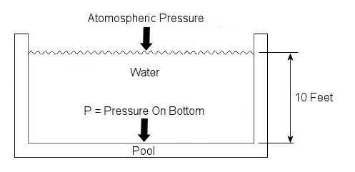
Last week we talked about basic concepts of fluid statics, using the example of a hydraulic jack. This week we’ll continue talking about fluid statics and explore another example. Let’s say you have a 10 foot deep swimming pool and you want to know what the water pressure is at its bottom. Your common sense may tell you that that pressure can be measured by examining the weight of the water itself, and you would be partially correct. But there is another factor that you may not have considered to be significant to the calculation. At this point let me pose a question. How do we breathe? Your answer is directly related to measuring that pressure at the bottom of the pool. You see, contrary to popular belief, air is not weightless, and because it has weight it impacts objects, creating an external pressure. This pressure is known as atmospheric, or barometric, pressure. When you breathe, your diaphragm, which is moved by a muscle, allows the lung cavities to expand or contract accordingly. When the diaphragm is lowered the lung cavities are increased in volume, allowing the atmospheric pressure of your surroundings to come rushing in to fill the space that has been created. Along those lines, it was discovered some time ago that in order to determine the pressure at a given point within a body of water, we must consider not only the depth of the water itself, but also the atmosphere that is above it, bearing down on it. This is illustrated in Figure 1.
Figure 1 – A Swimming Pool Filled With Water
In equation form, this relationship looks like this: P = (Atmospheric Pressure) + (The Specific Weight of Water) x (The Depth of the Water) Now, it’s known that atmospheric pressure at sea level is about 14.7 pounds per square inch. So let’s say that this is the pressure being exerted on the surface of the water in our example by the weight of the air above it. As for the second component of our equation, the water, its specific weight is held to be a constant of approximately 0.036 pounds force per cubic inch. Now there is only one thing left to do before solving our equation, and that is to convert the water’s depth from feet into inches. This must be done so that the units of depth (inches) match the units of specific weight (pounds force per cubic inch) in our calculation. The depth of the water would therefore be 10 feet times 12 inches per foot, or 120 inches. Now we can return to our equation, insert these values, and solve for the pressure at the bottom of the pool: P = 14.7 lbf/in2 + (0.036 lbf/in3) x (120 in) = 19.02 lbf/in2 = 19.02 psi, where “psi” is an abbreviation for pounds per square inch. Notice how the pressure at the bottom of the pool doesn’t depend on how wide or long the pool is? It only depends on its depth. This means the deeper into a body of water that you go, the more water weight will be bearing down upon you, that is to say, the water pressure increases. This is why submarine hulls have a propensity to collapse if they dive too deep. The pressure from the water above gets to be too great compared to the air pressure inside the submarine, and the metal of its hull stresses to the breaking point. It’s like squeezing an egg in your hand. This wraps things up for the topic of fluid statics. Next week we’ll continue with our fluid mechanics series and talk about fluid dynamics. This area of fluid mechanics involves fluids that move, like water moving through pipes and air flowing over airplane wings. _________________________________________________________________ |
Fluid Mechanics in Mechanical Engineering, Part I, Fluid Statics
Sunday, January 10th, 2010|
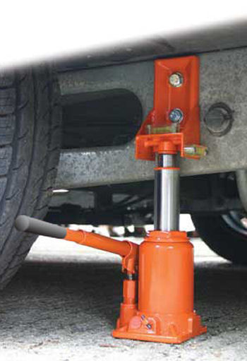
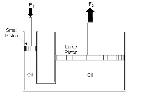
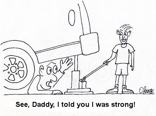
Last week we talked about psychrometry, which involves the analysis of gas and vapor mixtures like air and water. This week we’ll begin our discussion of fluid mechanics, which is the study of the force, pressure, and energy on both stationary and moving fluids. We’ll focus on stationary fluids this week. Let’s clear one thing up before we go any further. By “fluid,” I mean a substance that deforms continuously under a shearing stress, no matter how small. That means that when you try to cut it with a knife, a fluid just gives way under the knife and comes back together again after the knife passes through it. Remember the T-1000 liquid metal man in the movie Terminator II? Now that’s what I’m talking about! Now we all know that liquids are fluids, but did you know that gases are, too? An important concept in fluid mechanics is that liquids, like water and oil, cannot be compressed much when you push down on them in an enclosed container. This is because the molecules of liquids are tightly packed together and they can’t squeeze together any tighter. So, liquids are considered to be incompressible fluids. On the other hand, when you push down on a gas, take air for example, you can compress it within the container. This is because the gas molecules are far apart from each other, so there is plenty of room for them to come closer together. Since there is so much room between their molecules, gases are considered to be compressible fluids. Let’s begin our exploration of fluid mechanics by examining fluids that don’t move, meaning they are static. This field is also known as the study of fluid statics, otherwise known as hydrostatics. We’ll talk about fluids that move, that is, fluid dynamics, later in our series. To show how fluid statics works, suppose you have a hydraulic bottle jack in your garage like the one in Figure 1. When you push down on the lever, it doesn’t take a whole lot of muscle to lift something heavy like a car. Why is that? Let’s see how the jack works by looking at a cutaway diagram. See Figure 2.
Figure 1 – A Hydraulic Bottle Jack Used To Lift A Car
Figure 2 – Inside a Hydraulic Bottle Jack
The jack basically consists of two cylinders, one small, one large. The two cylinders are each filled with oil, and there is a passage between them. Inside each cylinder is a piston. The oil in the jack is a liquid, so it’s incompressible. When you push down on the jack’s lever, you create a force, F1, on the small piston. This then creates equal pressure in the oil under both the small and large pistons. Why? Because the liquid molecules are so tightly packed together, they push against each other and pressure is transmitted equally on all surfaces inside the jack. Now “pressure” is simply a force divided by a unit of area, for example, pounds of force per square inch. In our example it’s the large piston that’s going to lift the weight of the car. Because the large piston has a much larger surface area than the small piston, the fluid in the large cylinder will create a much larger force, F2, to bear up against the car’s weight, thereby lifting it off the ground. Now suppose the small piston has a surface area of 2 square inches, the large piston has a surface area of 20 square inches, and F1 is equal to 50 pounds of force. Since the oil pressure is equal under both pistons as stated above, we can write the flowing equation: Oil Pressure in the Small Piston = Oil Pressure in the Large Piston Once again, pressure is force divided by area, so for our hydraulic jack we can rewrite the equation as follows: (F1)/(Area of the Small Piston) = (F2)/(Area of the Large Piston) Okay, we’re in good shape here, because we know three things: F1, the area of the small piston, and the area of the large piston. So, by plugging this information into the equation, we can use algebra to solve for the upward force, F2, required to lift the car: (50lbf)/(2in2) = (F2)/(20in2) F2 = [(50lbf)/(2in2)] x (20in2) F2 = 500lbf = 500 Pounds of Force So what’s happened here? Well, like magic, the jack uses fluid statics to multiply the input force by a factor of ten. When you push down on the jack handle with 50 pounds of force, you actually produce 500 pounds of force, enough to lift the car. If you made the large piston wider, then its area would be much greater still. For example, if we doubled the size of the large piston from 20 square inches to 40 square inches, F2 would be doubled, so you’d end up with 1000 pounds of force, more than enough to lift an oversized vehicle, like an SUV. Miraculously, the force used to push down on the small piston would remain the same, so there’s no need to worry if you’re a 100-pound weakling. Next week we’ll continue with Part II of our discussion of Fluid Mechanics and talk further about fluid statics.
_________________________________________________________________
|
Thermodynamics in Mechanical Engineering, Part V, Psychrometry
Sunday, January 3rd, 2010|
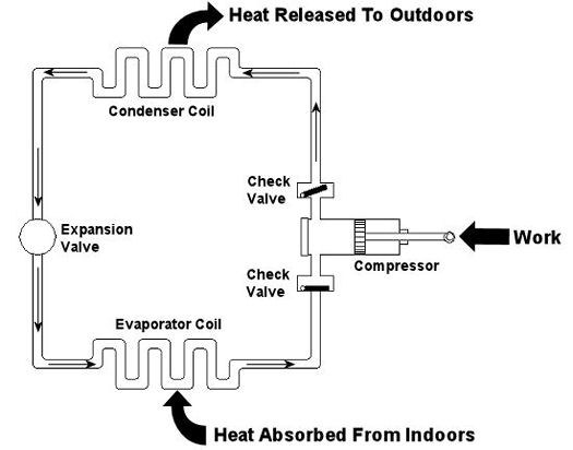
Last week we looked at the arithmetic behind chemical reactions in an area of thermodynamics known as stoichiometry. This week we’ll learn about psychrometry and the value of a summer breeze. Well, more specifically, psychrometry involves the analysis of gas and vapor mixtures, like air and water. You may not have ever heard of psychrometry or psychrometrics, but your body is familiar with it. In fact, it adheres to its principles every time it sweats. See, sweating keeps you cool, and that’s because when liquids like water evaporate, they absorb heat in the process. When sweat, which is mostly water, evaporates from your skin, it takes some of your body heat with it, dissipating it into the atmosphere. That’s why a roomful of sweaty bodies is so uncomfortable to be in. Now let’s say you’re outside and it’s a hot, humid summer day. The air already contains a lot of moisture, so it can’t absorb as much sweat from your body as it would in a drier environment. As a result, your sweat doesn’t evaporate so well. It lingers on your skin, keeping you miserable. Now introduce a summer breeze. The increase of air flow across your skin that it produces serves the same purpose as an electric fan in your home. They both make you cooler by increasing the surrounding air flow, thereby making more air available to contact your skin, and increasing the sweat evaporation process. In the study of psychrometry, mechanical engineers learn about the thermodynamic properties of moist air. Then they use these properties to analyze conditions and design processes which deal with moist air, things like air conditioning systems and dehumidifiers. Let’s return for a moment to that air conditioner example that we used in our discussion of Thermodynamics in Mechanical Engineering, Part III. This is shown in Figure 1 below. Psychrometry would be used here, too. For example, when you are determining how much heat must be removed from the warm, humid air inside your home by the evaporator coil inside your air conditioner. Knowing how much heat must be removed is one of the first steps to designing a system which is properly sized and works efficiently in order to keep you comfortable.
Figure 1 – A Simple Refrigeration Cycle
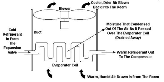
Psychrometric calculations can get pretty involved, and our discussion is meant to provide only a brief overview, but suffice it to say that their basic function is to set up a mass and energy accounting system that adheres to the principles of the First Law of Thermodynamics. In other words, energy and mass going into a system has to add up to energy and mass coming out. Now, let’s return to our discussion on psychrometry in relation to the design of the air conditioning system of Figure 1. Let’s focus on the evaporator coil from this system, as shown in Figure 2. This coil is contained in a duct along with a blower. The air sucked into the evaporator coil from the room has water vapor mixed into it. The pure air part and the water vapor part each contain heat energy. Our bodies perceive that heat energy as warm, humid air. As that humid air is cooled by the evaporator coil, much of the water vapor condenses out of it as liquid moisture, which is then drained out of the air conditioner. What’s left is a cooler mixture of air and greatly reduced water vapor. This mixture then leaves the evaporator coil and is sent back into your home from the duct by way of a blower, resulting in a more comfortable environment for you.
Figure 2 – An Evaporator Coil In An Air Conditioning Unit
So, using the First Law of Thermodynamics, the heat accounting system for the air conditioner looks like this: Qevaporator = (Qair + Qwater vapor)going in – (Qair + Qwater vapor + Qcondensed moisture)going out where, “Qevaporator” is the heat energy removed by the evaporator coil, “Qair” is the heat energy contained in the air, “Qwater vapor” is the heat energy contained in the water vapor, and “Qcondensed moisture” is the heat energy contained in the condensed moisture drained out of the air conditioner. By the way, the letter “Q” is often used to denote heat in thermodynamics. To solve for the equation above, one has to first consider what the pressure, temperature, and relative humidity of the air will be in the room when the air conditioner is first turned on. We must next determine what the desired pressure, temperature and relative humidity should ideally be once the conditioned air leaves the evaporator coil on its journey back into the room. In other words, we need to know the conditions we are starting out with in order to know where we want to end up, comfort-wise. Once these parameters are known, thermodynamic formulas are used to calculate how much heat must be removed by the evaporator coil. Now the air conditioning equipment can be designed with a large enough evaporator coil, with sufficient refrigerant flowing through it, and a large enough blower to efficiently perform the task of keeping us cool. This concludes our tour of the world of thermodynamics. Next week we’ll begin our discussion of an area of mechanical engineering known as fluid mechanics, which is the study of the force, pressure, and energy of both stationary and moving fluids. We’ll see how a hydraulic car jack works, how water flows through pipes, and how airplane wings lift a plane into the sky. _________________________________________________________________ |
Thermodynamics in Mechanical Engineering, Part IV, Stoichiometry
Sunday, December 27th, 2009|
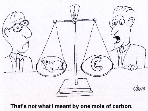
Last week we talked about an area of thermodynamics that concerns refrigeration cycles as presented through the example of an air conditioner. This week, we’ll learn about stoichiometry, which is concerned with the math behind chemical reactions, like those that take place during the burning of fuels. During the combustion process, heat energy is released from a fuel when the combustible elements in the fuel combine with oxygen. This is known as oxidation, or in common everyday language as burning. The most important thing to remember about oxidation is that it obeys the first law of thermodynamics. That is, mass cannot be created or destroyed. In a chemical reaction like combustion, particles of fuel and air are rearranged in space and then combine to form different substances. However, despite the rearranging, the mass that goes into the reaction must equal the mass that comes out. This conservation of mass is the basis of stoichiometry. For example, if pure carbon (represented by the chemical symbol “C”) is burned in pure oxygen (O2), you can represent the combustion process as: C + O2 → CO2 This is chemistry shorthand for representing how carbon and oxygen combine during burning to form carbon dioxide (CO2). The elements to the left of the arrow are known as “reactants” and the elements to the right are known as “products.” In stoichiometry, the mass of the reactants must equal the mass of the products. But, how do we quantify the mass of reactants and products? Now this is where it gets a little weird. To make use of our chemistry shorthand above, we have to consider something called moles. No, these aren’t the little furry creatures that tunnel under your lawn and eat your tulip bulbs. In stoichiometry a mole is considered to be 6.02×10²³ molecules of a substance. That is 602,000,000,000,000,000,000,000 molecules! Okay, so we have one heck of a lot of molecules in a mole. So, what does that have to do with figuring out how much mass we are dealing with in the combustion process? Well, in order to make moles work for us, we have to take into consideration the differing molecular weights of substances. Molecular weight is the number of grams (g) of mass that are contained within one mole of a substance, like the element carbon in our example above. To help make stoichiometry more workable, scientists created a table that provides the molecular weight of all known chemical elements. This table is known as the Periodic Table of Elements, or the “Periodic Table” for short. Now going back to our example above, if we know from the Periodic Table that carbon has a molecular weight of 12 g per mole and oxygen has a molecular weight of 16 g per mole, then how many grams of carbon dioxide do we get by burning carbon in pure oxygen? The combustion process can be represented by this equation: C + O2 → CO2 (12 g/mole) × (1mole of carbon) + (16 g/mole) × (2 moles of oxygen) = 44 g of carbon dioxide This is a fairly straightforward example of how stoichiometry works. In reality, things can get far more complicated. In a power plant for example, fuels like coal contain substances in addition to carbon, such as hydrogen and sulfur, and they, too, must be factored into the stoichiometric accounting system. To further complicate things, fuels are usually burned in air, rather than pure oxygen. Air, too, contains substances other than oxygen, including nitrogen, argon, and molecules of water. These other substances’ presence in fuel and air make the combustion process more challenging to account for, because they all get mixed together, and they can combine into all sorts of other substances. Despite these complicating factors, the first law of thermodynamics must be obeyed, so the balancing act is still the same: mass of the reactants must equal the mass of the products. Once mechanical engineers use stoichiometry to figure out what’s going in and coming out of the combustion process, they can then use the data provided by chemical analysis of the fuel to calculate the heat energy that is released. They can also calculate the air required for proper combustion. This helps them to design things capable of delivering enough fuel and air to meet the heat input requirements for a diversity of power cycles, from the engine in your car to the coal fired power plant supplying electricity for your home. Next week, we’ll talk about psychrometric analysis. No, this has nothing to do with psychiatry. Psychrometrics involves the analysis of gas and vapor mixtures like air and water. _________________________________________________________________ |
Thermodynamics In Mechanical Engineering, Part III, Refrigeration Cycles
Sunday, December 20th, 2009|
Last week we talked about an area of thermodynamics that concerns power cycles, an example of which can be found in a coal fired power plant. This week we’ll learn about another area of thermodynamics, that of refrigeration cycles. It’s been snowing in the Midwest, so the topic seems appropriate enough. A refrigeration cycle is obviously found in your refrigerator, but did you know that it’s also found in your air conditioner? Refrigeration cycles operate in Opposite Land as compared to power cycles. You know, the place where everything works in reverse. Instead of heat going into the cycle and electricity coming out, in a refrigeration cycle, electricity goes in and heat comes out—out of your refrigerator or air conditioned house, that is. Let’s consider an example of the simple air conditioner refrigeration cycle shown in Figure 1. The cycle has four important parts: an evaporator coil, a compressor, a condenser coil, and an expansion valve. All parts are connected by pipes, and the entire system is sealed up tight with refrigerant inside. Figure 1 – A Simple Refrigeration Cycle Used In An Air Conditioner The compressor is the heart of the operation, so to speak. In our simple cycle, the compressor consists of an electric motor-driven piston that moves back and forth within a cylinder. The motor does work as the piston moves back and forth, and the compressor pumps refrigerant through the pipes, the condenser coil, the expansion valve, and the evaporator coil. Like your heart, the pump has check valves that keep refrigerant flowing through the system in one direction (counterclockwise in our example). Keeping the flow going in one direction is critical to the operation of the cycle, as we’ll see in a moment. The refrigerant is the life blood of the cycle. It is a chemical that is manufactured to have special thermodynamic properties. For example, it’s really good at quickly absorbing a lot of heat at low temperature, like the temperature of the air in your house. The evaporator coil in Figure 1 would be located on the inside of your home. As the refrigerant enters the evaporator coil, it is a mixture of liquid and vapor. Inside the evaporator coil, the liquid refrigerant boils off to a vapor as it absorbs heat from the room. Yes, that’s right, the refrigerant boils at room temperature! The heat absorption in the evaporator is helped along by using a fan to push room air across its coil. Warm air from the room gets sucked into the air conditioner and cool air blows out into the room. But that’s not the end of the story. That heat from the room has to somehow get outside of the house, where it can be disposed of. This is so the refrigerant can pick up another load of heat when it flows back through the evaporator coil. But disposing of the heat from the refrigerant isn’t easy, since heat naturally wants to flow from a hotter place to a cooler place. So how do you buck Mother Nature and get heat to flow from the inside of your house where it’s cool to the outside of your house where it’s hotter? It takes work, and that’s where the compressor comes into play. The compressor first pulls the refrigerant vapor out of the evaporator and raises its pressure and temperature. This heart, like our own, is a hard worker. As the vapor leaves the compressor and passes through the condenser coil located outside your home, it is in a state where it can easily give up its heat to the warm air outside. The release of heat is helped along by the use of another fan that serves to push the outdoor air across the outside surfaces of the condenser coil. Then, as heat is released to the outdoor air, the refrigerant condenses back into a liquid. After leaving the condenser coil, the liquid refrigerant passes through the expansion valve, where its pressure and temperature are reduced. The refrigerant is now ready to pick up a new load of heat in the evaporator coil, and the cycle repeats itself with the help of a working electric motor. Next week, we’ll continue our exploration of thermodynamics and narrow our focus onto an area known as stoichiometry, which is concerned with the math behind chemical reactions, like those that take place during the burning of fuels. Math is fun. Just keep repeating that to yourself. _________________________________________________________________ |
Thermodynamics In Mechanical Engineering, Part II, Power Cycles
Sunday, December 13th, 2009|
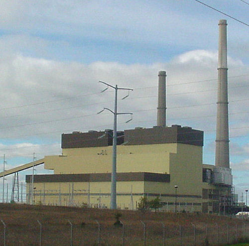
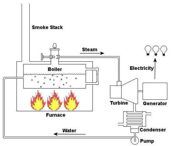
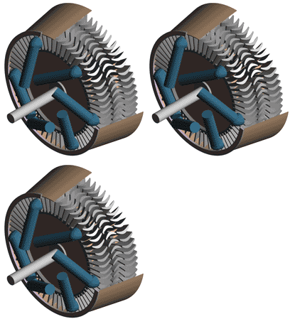
Last time we talked about some general concepts in an area of mechanical engineering known as thermodynamics. In this week’s article we’ll narrow our focus a bit to look at a part of thermodynamics that deals with power cycles. One mammoth example of a power cycle can be found in a coal-fired power plant. You can’t help but notice these plants with their massive buildings, mountains of coal, and tall smoke stacks. They’ve been getting a lot of negative press lately and are a central focus of the debate on global warming, but most people have no idea what’s going on inside of them. Let’s take a peek. Figure 1 – A Coal-Fired Power Plant A power plant has one basic function, to convert the chemical energy in coal into the electrical energy that we use in our modern lives, and it’s a power cycle that is at the heart of this conversion process. The most basic power cycle in this instance would include a boiler, steam turbine, condenser, and a pump (see Figure 2 below). Figure 2 – A Basic Power Cycle When the coal is burned in the power plant furnace, its chemical energy is turned into heat energy. This heat energy and the boiler are enclosed by the furnace so the boiler can more efficiently absorb the heat energy to make steam. A pipe carries the steam from the boiler to a steam turbine. Nozzles in the steam turbine convert the heat energy of the steam into kinetic energy, making the steam pick up speed as it leaves the nozzles. The fast moving steam transfers its kinetic energy to the turbine blades, causing the turbine to spin, much like a windmill (see Figure 3 below). Figure 3 – The Inner Workings of a Steam Turbine The spinning turbine is connected by a shaft to a generator. The turbine works to spin the generator and thus produces electricity. After the energy in the steam is used by the turbine, it goes to the condenser, whose job it is to convert the steam back into water. To accomplish this, the condenser uses cold water, say from a nearby lake or river, to cool the steam down until it converts from a gas back to a liquid, that is, water. This is why power plants are normally found adjacent to a body of water. After things are cooled down, the pump gets to work, pushing the condensed water back into the boiler where it is once again turned into steam. This power cycle keeps repeating itself as long as there is coal being burned in the furnace, the plant equipment is functioning properly, and electrical energy flows out of the power plant. Thermodynamics sets up an energy accounting system that enables mechanical engineers to design and analyze power cycles to make sure they are safe, reliable, efficient, and economical. When all is said and done, a properly designed power cycle transfers as much heat energy as possible from the burning coal on one end of the cycle to meet the requirements for electrical power on the other end of the cycle. As was mentioned in last week’s blog, nothing is 100% efficient. Next time we’ll learn about being cool. No, I’m not going to talk about the latest cell phone gadget or who’s connected on Facebook. We’ll be covering refrigeration cycles. _________________________________________________________________ |

