| Last time we began our look at the Production stage of systems engineering. We learned that cost reduction is a frequent component of this stage due to market fluctuations and ongoing stakeholder requirements to cut costs, and that savings can be made through substitution of plastic for metal parts. In fact, there are many faces to cost reduction. We’ll explore another of those today.
Cost reduction isn’t limited to material expense. Within the manufacturing process itself there are often ample opportunities for cost reduction. As an example let’s say we’re manufacturing a medical device known as a percussion therapy device on an assembly line employing 21 workers over three shifts. This line assembles 300 devices per day at a combined material and labor cost of $2,100 per unit. Percussion therapy devices are frequently used within the medical setting as they perform the very important function of helping to dislodge mucous from patients’ lungs. As such, they are in high demand and the market for them competitive. In our scenario some stakeholders in the device’s manufacture, in this case sales and marketing managers, specify that a cost reduction of $200 per device is necessary to avoid losing ground to competitors. In response to this directive, design engineers take a fresh look at the assembly process. They identified several bottlenecks at key junctures during which manual labor is involved. They note that due to the painstaking work required at these stages, production is slowed. Assembly lines operate dynamically, meaning any disturbance in the flow of activities has vast repercussions down the line. Bottlenecks in flow slow production lines, just as they do traffic on key arteries. A tie-up on assembly lines equates to production delays, and these may lead to difficulty in filling customer orders. Impatient customers have been known to turn to competitors when their orders aren’t filled, and this translates to lost revenue to our manufacturer. Next week we’ll see what manufacturing changes are employed to solve identified problems, and we’ll see how man’s best friend is not a dog, but a robot. ___________________________________________ |
Posts Tagged ‘metal parts’
Systems Engineering In Medical Device Design – Production, Part 2
Sunday, March 3rd, 2013Tags: assembly line, cost reduction, engineering expert witness, forensic engineer, manufacturing process, medical device design, metal parts, percussion therapy, plastic parts, Production Stage, stakeholder requirements, systems engineering
Posted in Engineering and Science, Expert Witness, Forensic Engineering, Innovation and Intellectual Property, Personal Injury, Product Liability, Professional Malpractice | Comments Off on Systems Engineering In Medical Device Design – Production, Part 2
Mechanical Power Transmission – The Centrifugal Clutch and Metal Fatigue
Sunday, May 13th, 2012|
When I’m under a lot of stress I sometimes have the nervous habit of grabbing a paper clip, straightening out the bends, then repetitively bending it back and forth. Eventually the wire reaches a point where it just breaks apart. My paper clip broke due to metal fatigue. Metal parts are said to become fatigued when they’re subjected to forces of a repetitive nature such as occur due to twisting and bending. The metal cracks, then eventually breaks due to the stress. So what’s happening when metal becomes fatigued? Figure 1 shows the simplified atomic structure of a sample metal. Figure 1
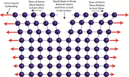
When the metal is deformed, such as during bending, its rows of atoms are forced to move with respect to each other as shown in Figure 2.
Figure 2
The movement of rows of atoms leads to an alteration in structure, breaking bonds between atoms. This results in small cracks forming along the metal’s surface, cracks which eventually migrate deeper inside the metal with each subsequent bend. With time the metal will become so compromised by the cracks that breakage occurs. Metal fatigue can occur in centrifugal clutch mechanisms as well. Power tools such as grass trimmers typically operate between idle and working speeds many times during a day’s usage. As we learned in previous articles, when the engine runs at idle speed, the springs in the centrifugal clutch mechanism stay retracted. As the engine speeds up, the centrifugal force acting on the clutch shoes extends the springs. Successive extensions and retractions cause the metal in the springs to bend, and over time they, like my paper clip, will become fatigued and metal springs will break. Next time we’ll continue talking about centrifugal clutch failures and learn how the springs of a clutch mechanism can fail without its metal being brought to the breaking point.
____________________________________________
|
Tags: atomic bonds, atomic structure, bending force, centrifugal clutch, clutch boss, clutch failure, clutch mechanism, clutch shoe, clutches, crack formation, engineering expert witness, forensic engineer, fracture, gasoline engine, grass trimmer, mechanical design, metal atoms, metal cracks, metal fatigue, metal parts, power tool, repetitive bending, springs, stress
Posted in Engineering and Science, Expert Witness, Forensic Engineering, Innovation and Intellectual Property, Personal Injury, Product Liability, Professional Malpractice | Comments Off on Mechanical Power Transmission – The Centrifugal Clutch and Metal Fatigue


