|
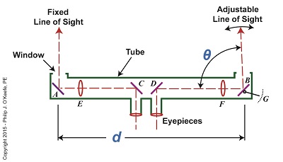
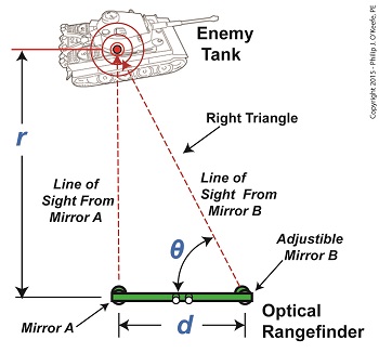
Last time we covered the mirrors found inside an optical rangefinder. Today we’ll discuss its other components, magnifying lenses E and F and the indicator gauge, G. See Figure 1. Figure 1 Magnifying lenses E and F are positioned in such a way that the two horizontal lines of sight reflecting off mirrors C and D pass through them on their way to mirrors A and B. Lenses E and F are adjustable, allowing the viewer to manipulate them until the distant image being viewed is seen in clear focus through both eyepieces, just as would happen with binoculars. To see the rangefinder in action let’s go out to the battlefield, where it’s routinely used. A soldier notices an enemy tank off in the distance. To make an accurate hit with his artillery he must determine the distance r from his position to the tank. The soldier in charge of this task observes the tank through the rangefinder’s eyepieces and manually adjusts lenses E and F until it comes into focus. He then adjusts the rangefinder’s mirror B until the line of sight extending from it converges on the tank along with the fixed line of sight from mirror A as shown in Figure 2. When the two images converge a right triangle is formed, and as we learned in a previous article, this fact will enable us to calculate r by using trigonometry with this formula: r = d × tan(θ) We already know that the value of d, the distance between mirrors A and B, is three feet. All that is left to be determined is the angle θ that’s formed between adjustable mirror B‘s forward line of sight out the tube’s opening and the horizontal line of sight between D and B. The last component within an optical rangefinder to be discussed is the indicator gauge, notated as G in Figure 1. This gauge is attached to mirror B inside the tube and is used to measure the angle θ that’s produced as the mirror is adjusted. When the lines of sight from mirrors A and B converge and the tank comes into clear view through the eyepieces, the value of θ can be read on the gauge’s numerical graduated scale, which is located on the exterior of the tube. Next time we’ll see how trigonometry and the study of right triangles prove indispensable when measuring distances with an optical rangefinder. ____________________________________
|
Posts Tagged ‘optical distance measurement’
What’s Inside an Optical Rangefinder
Friday, February 13th, 2015The Mirrors Inside an Optical Rangefinder
Friday, February 6th, 2015|
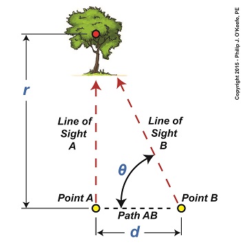
Last time we touched on the fact that humans require instruments to facilitate the optical measurement of distance to faraway objects, such as is represented by r in Figure 1. Figure 1 Today we’ll take a look at the mirrors inside an optical rangefinder, one of the devices that’s commonly used to measure great distances. The internal workings of an optical rangefinder are shown in Figure 2. Figure 2 The rangefinder’s body is a straight tube containing fixed mirrors, A, C, and D, and an adjustable mirror, B. Mirrors A and B in Figure 2 are analogous to Points A and B in Figure 1. For the sake of our example, we’ll say that the distance d in Figure 2 is equal to the distance d in Figure 1. This distance is three feet. The rangefinder functions similarly to a pair of binoculars, but with a twist — literally. Its four internal mirrors redirect the straight-ahead perspective that’s provided by the eyepieces into sideways orientations. Sight is deflected by mirrors C and D off to the left and right, respectively, as represented by red dashed lines. Finally, the lines of sight are once again aligned into straight-ahead orientations as they reflect off mirrors A and B and are guided out the openings at either end of the tube. Adjustable mirror B‘s line of sight is positioned at an angle that’s represented by the Greek letter θ, a symbol commonly used to represent angles in mathematics, engineering, and science. This angle is formed between mirror B’s line of sight and the horizontal line of sight traversing the expanse between mirrors D and B. The reason mirror B is an adjustable mirror is so that the line of sight extending from the opening at its location can converge into the line of sight provided by mirror A. Mirror B is manually manipulated until the image seen through it becomes one with A‘s image. Until this convergence takes place two separate images are seen through A and B. Next week we’ll see what happens when the images converge, and we’ll cover the remaining components within an optical rangefinder, items E, F, and G. ____________________________________
|
Parallax and Trigonometry
Monday, January 26th, 2015|
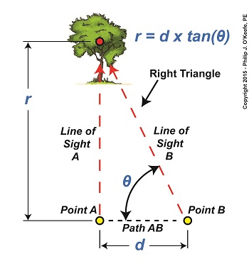
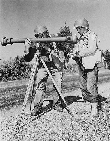
We’ve been working on a way to calculate the distance to a tree situated blocks from our viewing point. Flying raptors, such as our beloved bald eagle, wouldn’t find this in the least bit challenging. They’re able to accurately judge distances due to their special shape-shifting eye lenses which are capable of actually changing curvature spontaneously. But human physiology isn’t equipped for this task, so we’ll have to employ other methods. Today we’ll see how a branch of mathematics known as trigonometry comes into play. Referring to the illustration, we’d like to calculate the distance, r. You’ll note that a right triangle is formed by Line of Sight A, Path AB, and Line of Sight B. As mentioned in our last blog, right triangles are special because the relationship that exists between their sides and their internal angles is well defined within mathematics. In fact, we can calculate r by using this trigonometric formula, r = d × tan(θ) where d is the length of Path AB, θ is the angle between Line of Sight B and Path AB, and tan(θ) is the trigonometric function known as the tangent. Tangent, and other trigonometric functions like sine and cosine, relate the angles in a right triangle to the ratios of the lengths of the sides of the triangle. If we know two of the variables present in the equation presented above, we can determine the third, and the fact that there’s a right triangle present makes that task so much easier. As things stand now we have two unknowns, d and θ. As pointed out last week, the distance, d, is short, so we’ll use a tape measure to determine its length. Let’s say it measures out to be three feet. Now we need to solve for the angle θ that’s formed between Path AB and Line of Sight B. That’s a bit more challenging. There are a number of devices that can be used to measure θ, including a handheld magnetic compass. However, using a compass often yields inaccurate results, thereby increasing the likelihood of mistakes. A more accurate device to use would be an optical rangefinder, as shown below. The optical rangefinder is a device that’s often used in the military to measure long distances by using the principle of parallax. It functions much like binoculars do, but with a twist, literally, as we’ll see next time. ____________________________________
|
