|
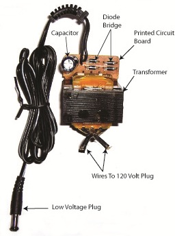
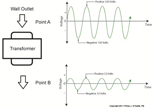
What would a cop show be without a crime scene, or better yet the obligatory dissection at the morgue? Forensic doctors performing autopsies have become commonplace, the clues they provide indispensable. Forensic engineers such as myself do much of the same thing, working our way backwards through time by dissecting industrial equipment and consumer products left in the wake of fires, injuries, and deaths. Let’s do some forensic dissecting now to see what’s in a wall wart and how it works. The inside of a basic wall wart is shown in Figure 1. Figure 1 – Inside The Wall Wart You’ll note that a wall wart has four main components: a transformer, diode bridge, capacitor, and a printed circuit board (PCB). The PCB is constructed of plastic resin upon which is mounted copper strips. This makes a rigid platform base upon which electronic components are attached, namely the transformer, diode bridge, and capacitor. These components are soldered to the PCB, tying them together both mechanically and electrically. Now let’s see how the components of the wall wart work together to change the 120 volts coming from your standard wall outlet into the 12 volts needed to power a typical electronic device. We’ll use an instrument known as an oscilloscope to help us visualize what’s going on. See Figure 2. Figure 2 – The Workings of the Wall Wart Transformer What is depicted in the graph above is the oscilloscope’s ability to receive an electronic signal, measure it, graph it, and then display it on a screen. This enables us to see how the signal changes over time. At Point A, which represents the wall wart plugged into a wall outlet, the voltage alternates between positive 120 volts and negative 120 volts upon entering the wall wart, which will now act as a transformer. The wall wart transformer then does as its name suggests, it transforms the 120 volts coming from the outlet into the 12 volts shown at Point B. You will note that this lower voltage also alternates between positive and negative values, just as the original 120 volts emanating from the wall outlet did. In one of my earlier blogs I explained that transformers only work when the electricity passing through them alternates over time. (Click here for a refresher: Transformers ) High voltage alternating electricity in one transformer coil creates magnetic fields that induce alternating electricity at a different voltage in a second transformer coil. So when you put alternating voltage into the transformer, you get alternating voltage out. But that’s not the end of the story. Many electronic devices operate on voltage that doesn’t alternate. What then? Will our handy wall wart still be able to bridge the electrical gap to fill our needs? Next time we’ll see how the diode bridge and capacitor come into play to deal with the alternating voltage from the transformer in a manner eerily similar to a microwave oven’s high voltage circuit. ____________________________________________ |
Posts Tagged ‘oscilloscope’
Inside The Wall Wart
Monday, September 5th, 2011The Microwave Oven — More on How AC Becomes DC
Monday, August 15th, 2011| The world of electricity is full of mysteries and often unanticipated outcomes, and if you’ve been reading along with my blog series you have been able to appreciate and come to some understanding of a fair number of them. This week’s installment will be no exception.
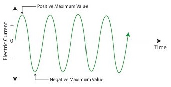
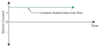
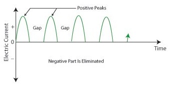
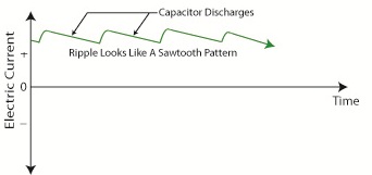
Last week we looked briefly at the high voltage circuit within a microwave oven. We discovered that the circuit contains a transformer that raises 120 volts alternating current (AC) to a much higher voltage, around 4000 volts AC. The circuit then transforms the AC into direct current (DC) with the help of electronic components known as a diode and capacitor. Let’s take a closer look at how the diode and capacitor work together to make AC into DC. Let’s follow an AC wave with the aid of a device called an oscilloscope. An oscilloscope takes in an electronic signal, measures it, graphs it, and shows it on a display screen so you can see how the signal changes over time. An AC wave is shown in Figure 1 as it would appear on an oscilloscope. Figure 1 – Alternating Current Wave You can see that each wave cycle starts with a zero value, climbs to a positive maximum value, then back to zero, and finally back down to a maximum negative value. The current keeps alternating between positive and negative polarity, hence the name “alternating current.” Within the microwave oven’s high voltage circuitry the transformer does the job of changing, or transforming if you will, 120 volts AC into 4000 volts AC. This high voltage is needed to make electrons leave the cathode in the magnetron and move them towards the anode to generate microwaves. But we’re not done with the transformation process yet. The magnetron requires DC to operate, not AC. DC current remains constant over time, maintaining a consistent positive value as shown in Figure 2. It is this type of consistency that the magnetron needs to operate. Figure 2 – Direct Current The microwave’s diode and capacitor work together to convert the 4000 volts AC into something which resembles 4000 volts DC. First the diode acts like a one-way valve, passing the flow of positive electric current and blocking the flow of negative current. It effectively chops off the negative part of the AC wave, leaving only positive peaks, as shown in Figure 3. Figure 3 – The Diode Chops Off The Negative Part of the AC Wave Between the peaks are gaps where there is zero current, and this is when the capacitor comes into play. Capacitors are similar to batteries because they can be charged with electrical energy and then discharge that energy when needed. Unlike a battery, the capacitor charges and discharges very quickly, within a fraction of a second. Within the circuitry of a microwave oven the capacitor charges up at the top of each peak in Figure 3, then, when the current drops to zero inside the gaps the capacitor comes into play, discharging its electrical energy into the high voltage circuit. The result is an elimination of the zero current gaps. The capacitor acts as a reserve energy supply to fill in the gaps between the peaks and keep current continually flowing to the magnetron. We have now witnessed a mock DC current situation being created, and the result is shown in Figure 4. Figure 4 – The Capacitor Discharges to Fill In The Gaps Between Peaks The output of this approximated DC current looks like a sawtooth pattern instead of the straight line of a true DC current shown in Figure 2. This ripple pattern is evidence of the “hoax” that has been played with the AC current. The net result is that the modified AC current, thanks to the introduction of the diode and energy storing capacitor, has made an effective enough approximation of DC current to allow our magnetron to get to work jostling electrons loose from the cathode and putting our microwave oven into action. You now have a basic understanding of how to turn AC into an effective approximation of DC current. Next week we’ll find out how this high voltage circuit can prove to be lethal, even when the microwave oven is unplugged. ____________________________________________ |
The Microwave Oven High Voltage Circuit—How AC Becomes DC
Sunday, August 7th, 2011| My mom was a female do-it-yourselfer. Toaster on the blink? Garbage disposal grind to a halt? She’d take them apart and start investigating why. Putting safety first, she always pulled the plug on electrical appliances before working on them. Little did she know that this safety precaution would not be enough in the case of a microwave oven. Let’s see how even an unplugged microwave can prove to be a lethal weapon and, yes, we’re going to have to get technical.
Last week we talked about the magnetron and how it needs thousands of volts to operate. To get this high of a voltage out of a 120 volt wall outlet–the voltage that most kitchen outlets provide–the microwave oven is equipped with electrical circuitry containing three important components: a transformer, a diode, and a capacitor, and just like the third rail of an electric railway system these items are to be avoided. If you decide to take your microwave oven apart and you come into contact with high voltage that is still present, you run the risk of injury or even death. But how can high voltage be present when it’s unplugged? Read on. First we need to understand how the 120 volts emitting from your wall outlet becomes the 4000 volts required to power a microwave’s magnetron. This change takes place thanks to a near magical act performed by AC, or alternating current. In the case of our microwave components, specifically its diode and capacitor, AC is made to effectively mimic the power of DC, or direct current, the type of current a magnetron needs. This transformation is made possible through the storage of electrical energy within the microwave’s capacitor. Next week we’ll examine in detail how this transformation from AC to DC current takes place, as seen through a device called an oscilloscope. ____________________________________________ |
