Posts Tagged ‘power plant’
Thursday, September 27th, 2018
|
Last time we introduced the phenomenon of uncontrollable factors as they exist within coal fired power plants. They inevitably result in lost energy in a number of ways, the most obvious of which is probably the smokestack, where lost energy is seen literally going up in smoke through the stack.
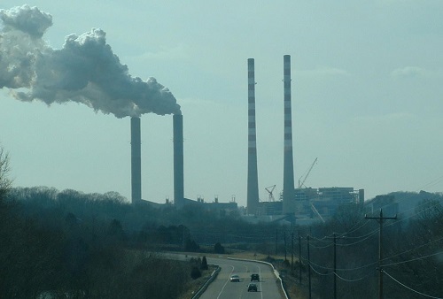
Energy Going up in Smoke Through the Stack
When coal is introduced into a coal fired power plant’s boiler, it’s combined with air, ignited, and begins to burn. This burning process releases some useful heat energy to fuel our power grids, but the rest goes up in smoke through the stack, releasing the products of the combustion process, including nitrogen, carbon monoxide, carbon dioxide, and water vapor into the atmosphere.
Next time we’ll discuss friction, another factor which results in power plant energy loss.
Copyright 2018 – Philip J. O’Keefe, PE
Engineering Expert Witness Blog
____________________________________ |
Tags: boiler, combustion process, energy, power plant, stack
Posted in Engineering and Science, Expert Witness, Forensic Engineering, Innovation and Intellectual Property, Personal Injury, power plant training | Comments Off on Energy Going up in Smoke Through the Stack
Wednesday, January 3rd, 2018
|
Shortly after I graduated with my engineering degree I worked as a power plant engineer at an electric utility. One day I was walking through the plant and heard a loud racket coming from the boiler feel pumps. These are the massive centrifugal pumps that deliver pressurized water to the boiler. The water is transformed into steam to drive steam turbines and spin electrical generators, which ultimately results in electrical power. The noise was so loud, it sounded like rocks were being ground up. I asked a coworker what was going on, and he replied matter-of-factly, “The pumps are cavitating.”
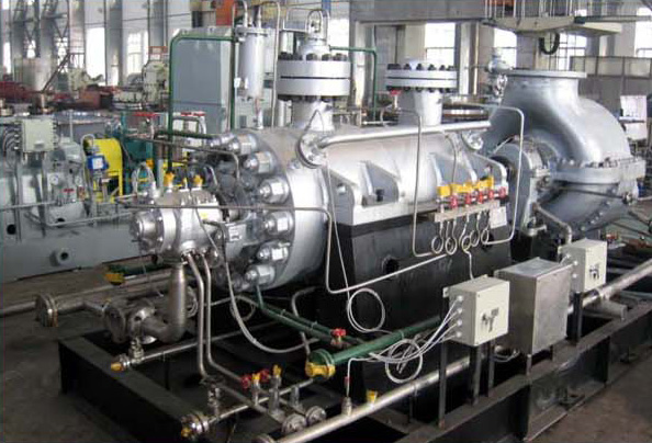
Boiler Feed Pumps Experience Cavitation
So what exactly is cavitation? We’ll find out next time when we explore the mechanics of this noisy phenomenon as it applies to boiler feed pumps and other centrifugal pumps.
opyright 2017 – Philip J. O’Keefe, PE
Engineering Expert Witness Blog
____________________________________ |
Tags: boiler, boiler feed pumps, cavitation, centrifugal pump, electric utility, electrical generator, engineering, power plant, steam turbine
Posted in Engineering and Science, Expert Witness, Forensic Engineering, Innovation and Intellectual Property, Personal Injury, power plant training, Product Liability | Comments Off on Boiler Feed Pumps Experience Cavitation
Saturday, October 24th, 2015
|
As an engineering expert with 14 years’ electric utility experience, I’ve dealt with all types of electrical power generators, including many similar to the dynamo that James Prescott Joule used in his Experiment With Electricity. Today we’ll look inside Joule’s dynamo and see how it contributed to creating electricity as well as another of Joule’s discoveries, the Joule Heating Effect.

Dynamo-Circa Early 19th Century
In Joule’s Experiment With Electricity, the dynamo was powered by a steam engine, which enabled the dynamo’s shaft to spin. As it spun, the magnet located inside the dynamo also spun, thus creating a rotating magnetic field that surrounded the dynamo’s internal copper wire coils.
The interaction between the magnetic field and wire produced electric current which flowed inside the coils. The current ultimately made its way out of the dynamo by way of external wires, to which any number of devices could be powered when attached. The net result was the engine’s mechanical energy had been converted into electrical. To learn more about the process of producing electricity with magnets see my blog on, Coal Power Plant Fundamentals – The Generator.
As electrical energy flowed through the dynamo’s wiring, some of it was converted into heat energy. This was due to resistance posed by impurities present in the makeup of the wire, impurities which served to impede the overall flow of electric current. When electrons flowing through the wire collided with these impediments, they caused heat to build up inside the wire, a phenomenon which came to be known as the Joule Heating Effect. To read more on electrical resistance and Joule heating go to my blog, Wire Size and Electric Current.
The net result of Joule’s Experiment With Electricity was to further prove the link between chemical, heat, mechanical and electrical energies as set out in the Law of Conservation of Energy. And I suspect that knowledge was later put to use by Joule’s family for the betterment of their brewery business.
Next time we’ll use Joule’s experimental findings in conjunction with de Coriolis’ Kinetic Energy Formula to quantify the energy of the falling coffee mug we’ve been watching.
Copyright 2015 – Philip J. O’Keefe, PE
Engineering Expert Witness Blog
____________________________________ |
Tags: de Coriolis, dynamo, electric utility, electrical energy, electrical power generators, electrical resistance, engineering expert, heat energy, James Prescott Joule, Joule heating, Joule's experiment with electricity, law of conservation of energy, power plant, wire size and electric current
Posted in Engineering and Science, Expert Witness, Forensic Engineering, Innovation and Intellectual Property, Personal Injury, power plant training, Product Liability | Comments Off on Joule’s Dynamo – The Joule Heating Effect
Friday, October 16th, 2015
|
In my work as an engineering expert I’ve dealt with all forms of energy, just as we’ve watched James Prescott Joule do. He constructed his Joule Apparatus specifically to demonstrate the connection between different forms of energy. Today we’ll see how he furthered his discoveries by building a prototype power plant capable of producing electricity, a device which came to be known as Joule’s Experiment With Electricity.

Joule’s Experiment With Electricity
As the son of a wealthy brewer, Joule had been fascinated by electricity and the possibility of using it to power his family’s brewery and thereby boost production. To explore the possibilities, he went beyond the Apparatus he had built earlier and built a device which utilized electricity to power its components. The setup for Joule’s experiment with electricity is shown here.
Coal was used to bring water inside a boiler to boiling point, which produced steam. The steam’s heat energy then flowed to a steam engine, which in turn spun a dynamo, a type of electrical generator.
Tracing the device’s energy conversions back to their roots, we see that chemical energy contained within coal was converted into heat energy when the coal was burned. Heat energy from the burning coal caused the water inside the boiler to rise, producing steam. The steam, which contained abundant amounts of heat energy, was supplied to a steam engine, which then converted the steam’s heat energy into mechanical energy to set the engine’s parts into motion. The engine’s moving parts were coupled to a dynamo by a drive belt, which in turn caused the dynamo to spin.
Next time we’ll take a look inside the dynamo and see how it created electricity and led to another of Joule’s discoveries being named after him.
Copyright 2015 – Philip J. O’Keefe, PE
Engineering Expert Witness Blog
____________________________________ |
Tags: boiler expert witness, dynamo, electric current, electric current induction, electrical energy, electrical engineering expert witness, electrical generator expert witness, electrical resistance of wires, engineering expert witness, forensic engineer, heat energy, James Prescott Joule, Joule Heating Effect, magnetic field, mechanical energy, mechanical engineering expert witness, power engineering expert witness, power plant, power plant engineering expert witness, steam, wire size
Posted in Engineering and Science, Expert Witness, Forensic Engineering, Innovation and Intellectual Property, Personal Injury, power plant training, Product Liability | Comments Off on Joule’s Experiment With Electricity
Tuesday, November 5th, 2013
|
Last time we discussed the key functions of the make-up valve in the power plant water-to-steam cycle. Today we’re going to talk about a vacuum. No, not the kind you use around the house, the kind that’s created by the condenser inside a power plant.
As discussed previously, the condenser is a piece of equipment that turns turbine exhaust steam back into water. The water that’s formed during this process is known as condensate, and its density is higher than that of the steam it shares space with inside the condenser. That difference in density is what creates the vacuum inside the condenser vessel. Put another way, the increase in density along with the condenser’s airtight design prevent air from rushing in from outside to occupy any of the space inside the condenser, a desirable condition from an efficiency standpoint.
But to understand how all this works we’ll first have to gain an understanding of what is meant by density. A textbook would define it as the mass of a substance divided by the amount of space that that substance occupies. Let’s take steam and water for example. One pound of steam at 212°F forms a vapor cloud that occupies 26.78 cubic feet of space. If we condensed that pound of steam back into water at the same temperature, it would just about fit into a 16 ounce glass and occupy a mere 0.017 cubic feet.

The huge difference in their volumes is due to the fact that steam contains more than five times the heat energy that unheated water does. That energy makes the molecules in a cloud of steam more active, causing them to collide against each other with great force, spread apart, and occupy a larger space.
If you’re wondering what change in density has to do with vacuum in the condenser, allow me to offer an analogy. Ever canned any produce, like tomatoes, in glass jars to over-winter? Not likely, as this once common survival tactic has nearly become a lost art. But the vacuum created inside the condenser is much like the vacuum created within a mason jar during canning.
Inside the glass mason jar, a small space is intentionally left between the tomatoes and lid. During the process of boiling, or heat sterilization, this space fills with steam. Then during cooling the trapped steam condenses into water. This condensation creates the vacuum that sucks down on the jar’s lid, giving it an airtight seal, a condition which won’t allow bacteria to grow on our canned foods. You see, like us bacteria need oxygen to live, but thanks to the vacuum inside our cooked mason jar no air containing oxygen will remain inside to harbor it.
Next time we’ll continue our discussion on vacuum to see how it’s used to increase a steam turbine’s efficiency.
________________________________________
|
Tags: coal power plant, condensate, condenser, density, electrical power, energy, engineering expert witness, forensic engineer, heat energy, make up valve, power engineer, power plant, power plant training, steam and water cycle, steam turbine efficiency, vacuum
Posted in Engineering and Science, Expert Witness, Forensic Engineering, Innovation and Intellectual Property, Personal Injury, power plant training, Product Liability | Comments Off on Vacuum in a Power Plant Condenser
Monday, October 28th, 2013
|
Last time we learned how the condenser recycles steam from the turbine exhaust by condensing it back into water for its reuse within the power plant steam-water cycle. This water is known as condensate, and after leaving the boiler feed pump at high pressure, it’s known as boiler feed water. Today we’ll introduce a special valve into the system, whose job it is to perform the important function of compensating for lost water. It’s known as the make-up valve.

The illustration shows the flow of steam and water within the cycle. Tracing the path of orange arrows will reveal it as a closed system.
Under ideal operating conditions recycled condensate from the condenser would provide enough water to keep the boiler indefinitely supplied. In reality water and steam leaks are a chronic problem within power plants, even when well maintained. Leaks typically occur due to worn parts on equipment, a condition which is commonly present due to the demanding operating conditions they must endure. First, there is the strain of continuous operation, then there are the high temperatures, typically greater than 1000°F, and high pressures that pipes, valves, pumps, and the boiler itself must endure. We’re talking about pressure higher than 2000 psi, that is, pounds per square inch. As a result, water levels within the boiler must periodically be replenished.
While tracing the arrows through the diagram, you would have come across the new make-up valve under discussion. It’s located on the pipe leading from the power plant’s water treatment system to the boiler feed pump. It’s normally kept closed, except under two circumstances, when the boiler is initially filled at startup, or when water replenishment needs to take place.
Due to water loss and difficult operating conditions, maintenance within the water-to-steam system of a power plant is a never ending task. There are miles of pipe connected to hundreds of pieces of equipment, all of which are distributed through a huge power plant structure. So the reality is that power plants operate with a continuous eye on leakage.
To contend with the leaks, human intervention is often required in the way of a boiler operator. Their job is to manually open the make-up valve to admit a fresh supply of water from the treatment plant to the boiler via the boiler feed pump. Once the system’s water requirements are replenished, the valve is once again closed.
Next time we’ll continue this series by discussing how the condenser enables the steam turbine to run more efficiently by creating a vacuum at the turbine’s exhaust.
________________________________________
|
Tags: boiler, boiler feed pump, closed system, coal-fired power plant, condensate, condenser, electric utility power plant, engineering expert witness, feed water, forensic engineer, high pressure, high temperature, make up valve, pipe, power engineer, power plant, power plant engineering expert witness, power plant maintenance, power plant operation, power plant training, pumps, start up, steam leaks, steam turbine, steam water cycle, turbine exhaust, vacuum, valves, water leaks, water to steam system, water treatment system
Posted in Engineering and Science, Expert Witness, Forensic Engineering, Innovation and Intellectual Property, Personal Injury, power plant training, Product Liability | Comments Off on The Make-up Valve in the Power Plant Steam to Water Cycle
Sunday, September 8th, 2013
|
Did you know that water droplets traveling at high velocity can take on the force of bullets? It can happen, particularly within steam turbines at a power plant during the process of condensation, where steam transforms back into water.
The last couple of weeks in this blog series we’ve been talking about the steam and water cycle within electric utility power plants, how heat energy is added to water during the boiling process, and how turbines run on the sensible heat energy that lies within the superheated steam vapor supplied by boilers and superheaters. We learned that without a superheater there is a very real possibility that the steam’s temperature can fall to mere boiling point.
When steam returns to boiling point temperature an undesirable situation is created. The steam begins to condense into water within the turbine. To understand how this happens, let’s return to our graph from last week. It illustrates the situation when there’s no superheater present in the power plant’s steam cycle.

Figure 1
After consuming all the sensible heat energy in phase C in Figure 1, the only heat energy which remains available to the turbine is the latent heat energy in phase B. If you recall from past blog articles, latent heat energy is the energy added to the boiler water to initiate the building of steam. As the turbine consumes this final source of heat energy, the steam begins a process of condensation while it flows through the turbine. You can think of condensing as a process that is opposite to boiling. During condensation, steam changes back into water as latent heat energy is consumed by the turbine.
When the condensing process is in progress, the temperature in phase B remains at boiling point, but instead of pure steam flowing through the turbine, the steam will now include water droplets, a dangerous mixture. As steam flows through the progressive chambers of turbine blades, more of its latent heat energy is consumed and increasingly more steam turns back into water as the number of water droplets increases.

Figure 2 – Water Droplets Forming in the Turbine
The danger comes in when you consider that the steam/water droplet mixture is flying through the turbine at hundreds of miles per hour. At these high speeds water droplets take on the force of machine gun bullets. That’s because they act more like a solid than a liquid due to their incompressible state. In other words, under great pressure and at high speed water droplets don’t just harmlessly splash around. They hit hard and cause damage to rapidly spinning turbine blades. Without a working turbine, the generator will grind to a halt.
So how do we supply the energy hungry turbine with the energy contained within high temperature superheated steam in sufficient quantities to keep things going? We’ll talk more about the superheater, its function and construction, next week.
________________________________________ |
Tags: boilers, boiling point, boiling process, bullets, coal power plant training, condensation, condense, damage, electric utility power plants, engineering expert witness, force, forensic engineer, generator, heat energy, high velocity, incompressible state, latent heat energy, licensed engineer, mechanical engineer, power engineer, power plant, sensible heat energy, steam, steam and water cycle, steam cycle, steam turbines, superheated steam vapor, superheater, superheaters, technical training, turbine blades, turbines, water, water droplets
Posted in Engineering and Science, Expert Witness, Forensic Engineering, Innovation and Intellectual Property, Personal Injury, power plant training, Product Liability | Comments Off on Condensation Inside the Steam Turbine
Monday, August 19th, 2013
|
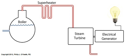
Last time we learned that our power plant boiler as presently designed doesn’t do a good job of producing ample amounts of superheated steam, the kind of steam that turbines need to spin and power generators. During the process of superheating the more heat energy that’s added to the steam in our boiler, the higher its temperature becomes. However, our boiler can only produce a limited amount of superheated steam as it stands now.

So how do we get more heat energy into the superheated steam? Take a look at the illustration below for the solution to the problem.

You’ll note a prominent new addition to our illustration. It’s called a superheater.
The superheater performs the function of raising the temperature of the steam produced in our boiler to the incredibly high temperatures required to run steam turbines and electrical generators down the line, as explained in my blog on steam turbines. The superheater adds more heat energy to the steam than the boiler can alone.
In fact, the amount of heat energy in the superheated steam produced with our new design is proportional to the amount of electrical energy that power plant generators produce. Its addition to our setup will result in more energy supplied to the turbine, which in turn spins the generator. The result is more electricity for consumers to use and a more efficiently operating power plant.
But inefficiency isn’t the only problem addressed by the superheater. We’ll see what else it can do next week.
________________________________________
|
Tags: boiler, coal power plant training, coal-fired power plant, efficiency, electrical energy, electrical generator, engineering expert witness, forensic engineer, generator, heat energy, power engineer, power plant, power plant engineer, power plant operations, steam temperature, steam turbine, superheated steam, superheater, superheating, turbine
Posted in Engineering and Science, Expert Witness, Forensic Engineering, Innovation and Intellectual Property, Personal Injury, power plant training | Comments Off on Superheating, Part I
Wednesday, August 14th, 2013
|
Last time we learned that electric utility power plants must have water treatment systems in place to remove contaminants from incoming feed water before it can be used. This clarified water is then fed to a boiler by the boiler feed pump as shown below.

As it stands this setup will work to provide electricity, however in this state it’s both inefficient and wasteful. We’ll see why in a minute.
Boilers, as their name implies, do a great job of heating water to boiling point to produce steam. They do this by adding the heat energy produced by burning fuel, such as coal, to water, then steam. We learned in earlier blogs in this series that the energy used to heat water to boiling point temperature is known as sensible heat, whereas the heat energy used to produce steam is known as latent heat. The key distinction between these two phases is that during sensible heating there is a rise in temperature, during latent heating there is not. For a review on this, see this blog article.
When water starts to heat inside the boiler, sensible heat energy is said to be added. This is represented by phase A of the graph below.

During A, heat energy will raise the temperature of the water to boiling point. As the water continues to boil in phase B, water is transforming into steam. During this phase latent heat energy is said to be added, and the temperature will remain at boiling point.
In phase C something new takes place. The temperature rises beyond boiling point and only steam is present. This is known as superheated steam. For example, if the boiler pressure is at 1,500 pounds per square inch, steam becomes superheated at temperatures greater than 600°F.
Unfortunately, boilers alone do a poor job of superheating steam, that is, continuing to raise the temperature of the steam present in phase C. This is evident by the fact that phase C is quite small in comparison to phases A and B before it. This inefficiency in producing ample amounts of superheated steam results in a small amount of useful energy being provided to the turbine down the line, which is bad, because steam turbines require exclusively superheated steam to run the generator.
Next time we’ll see how to provide our steam turbine with more of what it needs to run the generator, more superheated steam.
___________________________________________
|
Tags: boiler, boiler feed pump, boiler pressure, boiling point, contaminants, electric utility boiler expert witness, electrical generator, engineering expert witness, feed water, heat energy, latent heat, latent heat energy, power engineer, power plant, power plant engineering expert, power plant training, sensible heat, sensible heat energy, steam, steam turbine, superheated steam, superheating, turbine, water, water treatment system
Posted in Engineering and Science, Expert Witness, Forensic Engineering, Innovation and Intellectual Property, Personal Injury, power plant training | Comments Off on Heat Energy Within the Power Plant— Water and Steam Cycle, Part 2
Monday, December 12th, 2011
| You’ve probably heard the saying, “asleep at the switch.” It’s usually associated with some sort of disaster, found later to have been caused by human error. Someone wasn’t paying attention, and something very bad happened. The meltdown of the Soviet nuclear power plant Chernobyl in 1986 comes to mind. You may be surprised to learn that the saying has its origins in the world of industrial controls, or more specifically, manual controls, as we’ll see in this article.
Last week when we opened our discussion on manual controls, we talked about how they work just as their name implies, that is, someone must manually press a button or throw a switch in order to initiate a factory operation. In other words, a manual control requires human intervention to initiate an action, such as pushing the start button. The machine will then continue to run until a person hits the stop button.
Let’s go now on a virtual field trip into a telephone factory to see how a basic manual control system works. It has a conveyor belt operated by an electric motor, and this motor is connected by wires and a power switch to a 120 volt power source of alternating current. Figure 1 illustrates what we mean. It shows that when the power switch is in the open position, a physical air gap exists within the electrical circuit. This prevents electricity from flowing through the wire because electricity can’t jump over gaps.

Figure 1 – Open Power Switch
Enter a human into the scenario, someone who grabs the power switch handle and manually closes it, eliminating the air gap. See Figure 2.

Figure 2 – Closed Power Switch
When the power switch is closed, a metal conductor bridges the gap, causing electricity to flow through the metal conductor to the electric motor in the circuit. This brings life to the conveyor belt. As long as the power switch remains closed, the conveyor belt will continue to operate.
That’s it, that’s a basic manual control system. It’s simple to operate, but it does have one major flaw. It requires constant monitoring by a human. Aside from opening and closing a power switch, humans are required to monitor operations, in case something goes wrong. The operator watching over an industrial machine performs the same function as the pilot on a plane, that is, to start-stop operations, and to intervene in case of an emergency. Computers fly modern jets. Pilots serve as trouble shooters when the unanticipated disaster situation occurs, because computers can’t yet creatively problem solve.
Next time we’ll introduce the element of an automatic control system, which will virtually eliminate the need for human intervention and with it human error.
____________________________________________ |
Tags: air gap, alternating current, asleep at the switch, assembly line, control system, conveyor belt, electricity, electricity flow, engineering expert witness, factory, forensic engineer, industrial controls, machine, manual control, metal conductor, motor, operator, power plant, power source, power switch, production line, start button, stop button, telephone, wire
Posted in Engineering and Science, Expert Witness, Forensic Engineering, Innovation and Intellectual Property, Personal Injury, Product Liability, Professional Malpractice | Comments Off on Industrial Control Basics – Manual Control


