Posts Tagged ‘power’
Wednesday, December 6th, 2017
|
Last time we developed an engineering formula to calculate the horsepower required to accelerate a flywheel by way of a reciprocating steam engine, which contributes to the storage of kinetic energy inside a flywheel. Today we’ll gain a clearer understanding of how this works when we take a look inside a reciprocating steam engine.
A Look Inside a Reciprocating Steam Engine
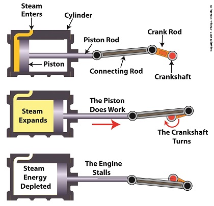
A reciprocating steam engine performs the work of transforming steam’s heat energy into the mechanical energy needed to move a piston contained within a cylinder. During a complete operating cycle this piston travels from one end of the cylinder to the other, then back again. This is made possible because during the first half of the cycle pressurized steam enters one end of the cylinder and expands inside it, forcing the piston to move.
This process inside the cylinder results in movement of a piston that’s attached to a piston rod, which in turn is connected to a crankshaft via a connecting rod and crank rod. The crankshaft is a device which converts the reciprocating linear motion of an engine’s piston into rotary motion and in so doing facilitates the powering of any externally mounted rotating machinery attached to it. So long as there’s ample steam to power the internal piston, over time, energy in the form of horsepower will be available to externally mounted devices. The energy in the steam decreases as the steam expands behind the moving piston. So, the engine’s horsepower, will decrease as the piston travels to the end of the cylinder. If the energy in the steam should become depleted, the reciprocating steam engine will stall. The engine will no longer be able to perform work.
Next time we’ll see how a crankshaft works when we take a look inside it.
opyright 2017 – Philip J. O’Keefe, PE
Engineering Expert Witness Blog
____________________________________ |
Tags: connecting rod, crank rod, crankshaft, energy, engineering, flywheel, kinetic energy, piston rod, power, reciprocating steam engine, work
Posted in Engineering and Science, Expert Witness, Forensic Engineering, Innovation and Intellectual Property, Personal Injury, Product Liability | Comments Off on A Look Inside a Reciprocating Steam Engine
Saturday, July 29th, 2017
|
Last time we determined the value for one of the key variables in the Euler-Eytelwein Formula known as the angle of wrap. To do so we worked with the relationship between the two tensions present in our example pulley-belt assembly, T1 and T2. Today we’ll use physics to solve for T2 and arrive at the Mechanical Power Formula, which enables us to compute the amount of power present in our pulley and belt assembly, a common engineering task.
To start things off let’s reintroduce the equation which defines the relationship between our two tensions, the Euler-Eytelwein Formula, with the value for e, Euler’s Number, and its accompanying coefficients, as determined from our last blog,
T1 = 2.38T2 (1)
Before we can calculate T1 we must calculate T2. But before we can do that we need to discuss the concept of power.
The Mechanical Power Formula in Pulley and Belt Assemblies
Generally speaking, power, P, is equal to work, W, performed per unit of time, t, and can be defined mathematically as,
P = W ÷ t (2)
Now let’s make equation (2) specific to our situation by converting terms into those which apply to a pulley and belt assembly. As we discussed in a past blog, work is equal to force, F, applied over a distance, d. Looking at things that way equation (2) becomes,
P = F × d ÷ t (3)
In equation (3) distance divided by time, or “d ÷ t,” equals velocity, V. Velocity is the distance traveled in a given time period, and this fact is directly applicable to our example, which happens to be measured in units of feet per second. Using these facts equation (3) becomes,
P = F × V (4)
Equation (4) contains variables that will enable us to determine the amount of mechanical power, P, being transmitted in our pulley and belt assembly.
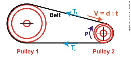
The force, F, is what does the work of transmitting mechanical power from the driving pulley, pulley 2, to the passive driven pulley, pulley1. The belt portion passing through pulley 1 is loose but then tightens as it moves through pulley 2. The force, F, is the difference between the belt’s tight side tension, T1, and loose side tension, T2. Which brings us to our next equation, put in terms of these two tensions,
P = (T1 – T2) × V (5)
Equation (5) is known as the Mechanical Power Formula in pulley and belt assemblies.
The variable V, is the velocity of the belt as it moves across the face of pulley 2, and it’s computed by yet another formula. We’ll pick up with that issue next time.
Copyright 2017 – Philip J. O’Keefe, PE
Engineering Expert Witness Blog
____________________________________ |
Tags: belt, distance divided by time, engineering, Euler-Eytelwein Formula, Euler's Number, force, loose side tension, mechanical power, mechanical power formula, power, power transmitted, pulley, tight side tension, velocity, work
Posted in Engineering and Science, Expert Witness, Forensic Engineering, Innovation and Intellectual Property, Personal Injury, Product Liability | Comments Off on The Mechanical Power Formula in Pulley and Belt Assemblies
Tuesday, June 13th, 2017
|
Last week we saw how friction coefficients as used in the Euler-Eyelewein Formula, can be highly specific to a specialized application, U.S. Navy ship capstans. In fact, many diverse industries benefit from aspects of the Euler-Eytelwein Formula. Today we’ll introduce another engineering application of the Formula, exploring its use within the irrigation system of a hydroponics plant.
Another Specialized Application of the Euler-Eyelewein Formula
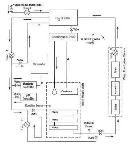
Pumps conveying water are an indispensable part of a hydroponics plant. In the schematic shown here they are portrayed by the symbol ⊗.
In our simplified scenario to be presented next week, these pumps are powered by a mechanical power transmission system, each consisting of two pulleys and a belt. One pulley is connected to a water pump, the other pulley to a gasoline engine. A belts runs between the pulleys to deliver mechanical power from the engine to the pump.
The width of the belts is a key component in an efficiently running hydroponics plant. We’ll see how and why that’s so next time.
Copyright 2017 – Philip J. O’Keefe, PE
Engineering Expert Witness Blog
____________________________________ |
Tags: belt, belt width, coefficient of friction, engineering, Euler-Etytelwein Formula, gasoline engine, hydroponics, mechanical power transmission, power, pulley, pump
Posted in Engineering and Science, Expert Witness, Forensic Engineering, Innovation and Intellectual Property, Personal Injury, Product Liability, Professional Malpractice | Comments Off on Another Specialized Application of the Euler-Eyelewein Formula
Tuesday, November 3rd, 2015
|
When acting as an engineering expert I’m often called upon to investigate incidents where energy converts from one form to another, a phenomenon that James Prescott Joule observed when he built his apparatus and performed his experiments with electricity. Today we’ll apply Joule’s findings to our own experiment with a coffee mug when we convert its kinetic energy into electrical energy and see how the units used to express that energy also change.
We had previously calculated the kinetic energy contained within our falling coffee mug to be 4.9 kg • meter2/second2, also known as 4.9 Joules of energy, by using de Coriolis’ Kinetic Energy Formula. Now most of us don’t speak in terms of Joules of energy, but that’s easily addressed. As we learned in a previous blog on The Law of Conservation of Energy, all forms of energy are equivalent and energy can be converted from one form to another, and when it does, the unit of energy used to express it also changes.
Let’s say we want to put our mug’s 4.9 Joules of kinetic energy to good use and power an electric light bulb. First we must first find a way of converting the mug’s kinetic energy into electrical energy. To do so, we’ll combine Joule’s apparatus with his dynamo, and connect the mug to this hybrid device with a string.
![]() 
Converting Kinetic Energy to Electrical Energy
As the mug falls its weight tugs on the string, causing the winding drum to rotate. When the drum rotates, the dynamo’s magnet spins, creating electrical energy. That’s right, all that’s required to produce electricity is a spinning magnet and coils of wire, as explained in my previous blog, Coal Power Plant Fundamentals – The Generator.
Now we’ll connect a 5 Watt bulb to the dynamo’s external wires. The Watt is a unit of electrical energy named in honor of James Watt, a pioneer in the development of steam engines in the late 18th Century.
Now it just so happens that 1 Watt of electricity is equal to 1 Joule of energy per a specified period of time, say a second. This relationship is expressed as Watt • second. Stated another way, 4.9 Joules converts to 4.9 Watt • seconds of electrical energy. Let’s see how long we can keep that 5 Watt bulb lit with this amount of energy. Mathematically this is expressed as,
Lighting Time = (4.9 Watt • seconds) ÷ (5 Watts) = 0.98 seconds
This means that if the mug’s kinetic energy was totally converted into electrical energy, it would provide enough power to light a 5 Watt bulb for almost 1 second.
Next time we’ll see what happens to the 4.9 Joules of kinetic energy in our coffee mug when it hits the floor and becomes yet another form of energy.
Copyright 2015 – Philip J. O’Keefe, PE
Engineering Expert Witness Blog
____________________________________ |
Tags: coils of wire, dynamo, electrical energy, engineering, engineering expert, James Prescott Joule, James Watt, joule, kinetic energy, magnet, power, watt seconds, wires
Posted in Engineering and Science, Innovation and Intellectual Property, power plant training | Comments Off on Converting Kinetic Energy to Electrical Energy
Wednesday, December 4th, 2013
|
Last time we ran our basic power plant steam turbine without a condenser. In that configuration the steam from the turbine exhaust was simply discharged to the surrounding atmosphere. Today we’ll connect it to a condenser to see how it improves the turbine’s efficiency.

As discussed in a previous blog, enthalpy h1 is solely dependent on the pressure and temperature at the turbine inlet. For purposes of today’s discussion, turbine inlet steam pressure and temperature will remain as last time, with values of 2,000 lbs PSI and 1000°F respectively, and calculations today will be based upon those values. So to review, the inlet enthalpy h1 is,
h1 = 1474 BTU/lb
If the condenser vacuum exists at a pressure of 0.6 PSI, a realistic value for a power plant condenser, then referring to the steam tables in the Van Wylen and Sonntag thermodynamics book, we find that the enthalpy h2 will be,
h2 = 847 BTU/lb
and the amount of useful work that the turbine can perform with the condenser in place would therefore be,
W = h1 – h2 = 1474 BTU/lb – 847 BTU/lb = 627 BTU/lb
So essentially with the condenser present, the work of the turbine is increased by 168 BTU/lb (627 BTU/lb – 459 BTU/lb). To put this increase into terms we can relate to, consider this. Suppose there’s one million pounds of steam flowing through the turbine each hour. Knowing this, the turbine power increase, P, is calculated to be,
P = (168 BTU/lb) ´ (1,000,000 lb/hr) = 168,000,000 BTU/hr
Now according to Marks’ Standard Handbook for Mechanical Engineers, a popular general reference book in mechanical engineering circles, one BTU per hour is equivalent to 0.000393 horsepower, or HP. So converting turbine power, P, to horsepower, HP, we get,
P = (168,000,000 BTU/hr) ´ (0.000393 HP/BTU/hr) = 66,025 HP
A typical automobile has a 120 HP engine, so this equation tells us that the turbine horsepower output was increased a great deal simply by adding a condenser to the turbine exhaust. In fact, it was increased to the tune of the power behind approximately 550 cars!
What all this means is that the stronger the vacuum within the condenser, the greater the difference between h1 and h2 will be. This results in increased turbine efficiency and work output, as evidenced by the greater numeric value for W. Put another way, the turbine’s increased efficiency is a direct result of the condenser’s vacuum forming action and its recapturing of the steam that would otherwise escape from the turbine’s exhaust into the atmosphere.
This wraps up our series on the power plant water-to-steam cycle. Next time we’ll use the power of 3D animation to turn a static 2D image of a centrifugal clutch into a moving portrayal to see how it works.
________________________________________
|
Tags: automobile engine, BTU, BTU/lb, coal power plant, energy, engineering expert witness, enthalpy, forensic engineer, horsepower, mechanical engineer, power, power engineer, power industry expert, power plant efficiency, power plant expert, power plant training instructor, power plant training seminars, steam pressure, steam turbine, steam turbine expert witness, steam water cycle, thermodynamics, vacuum, work
Posted in Engineering and Science, Expert Witness, Forensic Engineering, Innovation and Intellectual Property, Personal Injury, power plant training, Product Liability, Professional Malpractice | Comments Off on How Condensers Increase Efficiency Inside Power Plants
Monday, September 2nd, 2013
|
Last time we learned that the addition of a superheater to the electric utility power plant steam cycle provides a ready supply of high temperature steam, laden with heat energy, to the turbine, which in turn powers the generator. But this isn’t its only job. One of the superheater’s most important functions is to regulate the ongoing process of desuperheating that takes place as the turbine consumes heat energy. To understand this, let’s see what takes place if the superheater were to be removed from its position between the boiler and turbine.

Figure 1
Without the superheater, the only available remaining source of sensible heat energy to the turbine would come from the meager amount present in phase C steam as shown in Figure 1. If you’ll recall from a past blog, the sensible heat energy contained in superheated steam is the best source of energy for a steam turbine, because it’s able to keep it operating most efficiently.
As the turbine consumes the heat energy in phase C, starting at point 3 and continuing to point 2, the steam it’s consuming is in the process of desuperheating, as evidenced by the downward slope between the two points. Desuperheating is an engineering term which means that as sensible heat energy is removed from the steam due to its use by the turbine, there will be a resulting drop in steam temperature. And if this process were to continue without the compensatory function provided by the addition of a superheater to the steam cycle, the steam’s temperature would eventually return to mere boiling point, at point 2. This is an undesirable thing.
With the steam’s temperature at boiling point, the only remaining source of heat energy to the turbine is the latent heat energy of phase B. This heat energy will lead to an undesirable circumstance for the operation of our power hungry turbine as we will see next week.
________________________________________ |
Tags: boiler, desuperheat, desuperheating, electric utility power plant, engineering expert witness, forensic engineer, generator, heat energy, latent heat energy, power, power plant engineering, power plant training, sensible heat energy, steam cycle, steam temperature, steam turbine, superheated steam, superheater, temperature
Posted in Engineering and Science, Expert Witness, Forensic Engineering, Innovation and Intellectual Property, Personal Injury, power plant training | Comments Off on Desuperheating in the Steam Turbine
Monday, August 5th, 2013
|
Last time we learned that electric utility power plant boilers are vessels that are reinforced with thick steel and are closed off from the surrounding atmosphere so as to facilitate the building up of highly pressurized steam. This steam is laden with sensible heat energy, meaning it’s a useful energy, and it’s used to run steam turbines, which in turn drive electrical generators. The end result is power to consumers.
Let’s now revisit our basic electric utility boiler diagram to see how water and steam flow.

Water is fed into the boiler, heat is applied externally, and steam exits through a pipe leading to the steam turbine. You’ll notice that after the steam passes through the turbine, some of it is expelled into the surrounding atmosphere.
Since water is being continuously boiled off to produce steam, the boiler must be continuously replenished with a fresh supply. This is typically supplied by a nearby body of water, hence one reason that power plants are often situated on a lake or river.
Since water contains both minerals and organic matter, including algae, a treatment system to remove these contaminants must be added to the water’s inlet area before it can be used. This will keep operating parts such as the boiler and turbine free of damaging deposits.

The treatment system operates much like the water softener in your home, but on a larger scale. Lake water is drawn into the system by a make-up pump, so named because it makes up, or replenishes spent water with a fresh supply. The result is clean, mineral-free water that’s delivered to the boiler by a boiler feed pump, so named because its specific function is to feed water to the boiler.
Feeding water to the boiler on a continuous basis is no easy task because of the steam straining to break free, and boiler feed pumps are massively powerful devices built to accomplish this. They effectively force water into the boiler even as high internal pressures try to force the water out. This pressure is often greater than 1,500 pounds per square inch (PSI) in modern power plants.
So at this point we’ve discussed the fact that the boiler requires a continuous supply of fresh water, which is converted into high pressure steam, which is then sent on to spin a steam turbine. The turbine powers an electrical generator, resulting in usable energy.
If you’ve been reading along closely, you will have identified that as things stand now it’s a rather inefficient and wasteful system, a point which we’ll address in next week’s blog.
___________________________________________
|
Tags: boiler, boiler feed pump, certified model law engineer, coal power plant training seminars, degreed mechanical engineer, electric utility boiler, electric utility power plant boilers, electrical generators, engineering expert witness, feedwater, forensic engineer, high internal pressures, highly pressurized steam, licensed professional engineer, make-up pump, modern power plants, power, sensible heat energy, steam turbine, steam turbines, vessels, water treatment system
Posted in Engineering and Science, Expert Witness, Forensic Engineering, Innovation and Intellectual Property, Personal Injury, power plant training, Product Liability | Comments Off on Heat Energy Within the Power Plant – Water and Steam Cycle, Part 1
Monday, November 12th, 2012
|
Last time we learned about a new type of transistor called a bipolar transistor and how it controls the flow of electric current traveling from the collector to the emitter within our circuit. We also saw how the bipolar transistor is integrated within a Zener diode voltage regulator circuit to make a new type of circuit called a transistor series voltage regulator.
Now let’s see how this all works by hooking our circuit up to both an unregulated power supply and an external supply circuit as shown in Figure 1.

Figure 1
When voltage VUnregulated is applied to our transistor series voltage regulator circuit by way of an unregulated power supply, electric current flows through RLimiting into the base, B, of the transistor. The transistor senses this current and responds by opening a path for current to flow from its collector, C, to its emitter, E. With this path established, current flows freely from the unregulated power supply, through the transistor’s collector and emitter, on to the output terminal, and finally to the external supply circuit. Total resistance of this circuit is said to be RTotal.
At this point you’re probably wondering why the bipolar transistor base and Zener diode are connected to RLimiting. Next time we’ll conclude our series by seeing how this connection is crucial to the functionality of our transistor series voltage regulator.
____________________________________________
|
Tags: base, bipolar transistor, circuit, collector, emitter, engineering expert witness, forensic engineer, power, power supply, regulated voltage supply, resistor, transistor series voltage regulator, unregulated voltage supply, voltage regulation, Zener diode
Posted in Engineering and Science, Expert Witness, Forensic Engineering, Personal Injury, Product Liability | Comments Off on Transistors – Voltage Regulation Part XVII
Tuesday, January 3rd, 2012
| I’ve always considered science to be cool. Back in the 5th grade I remember fondly leafing through my science textbook, eagerly anticipating our class performing the experiments, but we never did. For some reason my teacher never took the time to demonstrate any. Undeterred, I proceeded on my own.
I remember one experiment particularly well where I took a big steel nail and coiled wire around it. When I hooked a battery up to the wires, as shown in Figure 1 below, electric current flowed from the battery through the wire coil. This set up a magnetic field in the steel nail, thereby creating an electromagnet. My electromagnet was strong enough to pick up paper clips, and I took great pleasure in repeatedly picking them up, then watching them unattach and fall quickly away when the wires were disconnected from the battery.

Figure 1
Little did I know then that the electromagnet I had created was similar to an important part found within electrical relays used in many industrial control systems. An example of one of these relays is shown in Figure 2.

Figure 2
So, what’s in the little plastic cube? Well, a relay is basically an electric switch, similar to the ones we’ve discussed in the past few weeks, the major difference being that it is not operated directly by human hands. Rather, it’s operated by an electromagnet. Let’s see how this works by examining a basic electrical relay, as shown in Figure 3.

Figure 3
The diagram in Figure 3 shows a basic electric relay constructed of a steel core with a wire coil wrapped around it, similar to the electromagnet I constructed in my 5th grade experiment. If the coil’s wires are not hooked up to a power source, a battery for example, no electric current will flow through it. When there is no current the coil and steel core are not magnetic. For purposes of our illustration and in accordance with industrial control parlance, this is said to be this relay’s “normal state.”
Next to the steel core there is a movable steel armature, a kind of lever, which is attached to a spring. On one end of the armature is a pivot point, on the other end is a set of electrical switch contacts. When the relay is in its normal state, the spring’s tension holds the armature against the “normally closed,” or N.C., contact. If electric current is applied to the wire leading to the pivot point on the armature while in this state, it will be caused to flow on a continuous path through the armature and the N.C. contact, then out through the wire leading from the N.C. contact. In our illustration, since the armature does not touch the N.O. contact, an air gap is created that prevents electric current from traveling through the contact from the armature.
Next week we’ll see how these parts come into play within a relay when electric current flows through the coil, turning it into an electromagnet.
____________________________________________ |
Tags: armature, control system, electric current, electric relay, electrical switch contacts, electromagnet, electromechanical relay, engineering expert witness, forensic engineer, industrial control, magnet, magnetic steel core, normal state, normally closed, normally open, power, relay, relay logic, spring, steel core, switch, switch contact, wire, wire coil
Posted in Engineering and Science, Expert Witness, Forensic Engineering, Innovation and Intellectual Property, Personal Injury, Product Liability, Professional Malpractice | Comments Off on Industrial Control Basics – Introduction to Electric Relays
Sunday, March 20th, 2011
| Ever take a peek inside the toaster while you’re waiting for the toast to pop up? If so, you would have noticed a bright orange glow. That glow is produced when the toasting wires heat up, which in turn creates a nice crusty surface on your bread or waffle. It’s the same phenomenon as when the filament inside an incandescent bulb glows. The light and heat produced in both these cases are the result of the Joule, pronounced “jewel,” effect at work.
To understand Joule heating, let’s first refresh our memories as to electrical current resistance. We learned previously that wire is not a perfect conductor, and as such resistance to flow is encountered. This resistance causes power to be lost along the length of wire, in accordance with this equation:
Power Loss = I2 × R
Where I is the electric current flowing through a wire, and R is the total electrical resistance of the wire. The power loss is measured in units of Joules per second, otherwise known as watts, “watt” denoting a metric unit of power. It is named after the famed Scottish mechanical engineer, James Watt, who is responsible for inventing the modern steam engine. A Joule is a metric unit of heat energy, named after the English scientist James Prescott Joule. He was a pioneer in the field of thermodynamics, a branch of physics concerned with the relationships between different forms of energy.
Anyway, to see how the equation works, let’s look at an example. Suppose we have 12 feet of 12 AWG copper wire. We are using it to feed power to an appliance that draws 10 amperes of electric current. Going to our handy engineering reference book, we find that the 12 AWG wire has an electrical resistance of 0.001588 ohms per foot, “ohm” being a unit of electrical resistance. Plugging in the numbers, our equation for total electrical resistance becomes:
R = (0.001588 ohms per foot) × 12 feet = 0.01905 ohms
And we can now calculate power loss as follows:
Power = I2 × R = (10 amperes)2 × (0.01905 ohms) = 1.905 watts
Instead of using a 12 AWG wire, let’s use a smaller diameter wire, say, 26 AWG. Our engineering reference book says that 26 AWG wire has an electrical resistance of 0.0418 ohms per foot. So let’s see how this changes the power loss:
R = (0.0418 ohms per foot) × 12 feet = 0.5016 ohms
Power = I2 × R = (10 amperes)2 × (0.5016 ohms) = 50.16 watts
This explains why appliances like space heaters and window unit air conditioners have short, thick power cords. They draw a lot of current when they operate, and a short power cord, precisely because it is short, poses less electrical resistance than a long cord. A thicker cord also helps reduce resistance to power flow. The result is a large amount of current flowing through a superhighway of wire, the wide berth reducing both the amount of power loss and the probability of dangerous Joule heating effect from taking place.
Our example shows that the electric current flowing through the 12 AWG wire loses 1.905 watts of power due to the inconsistencies within the wire, and this in turn causes the wire to heat up. This is Joule heating at work. Joule heating of 50.16 watts in the thinner 26 AWG wire can lead to serious trouble.
When using a power cord, heat moves from the copper wire within it, whose job it is to conduct electricity, and beyond, on to the electrical insulation that surrounds it. There the heat is not trapped, but escapes into the environment surrounding the cord. If the wire has low internal resistance and the amount of current flowing through it is within limits which are deemed to be acceptable, then Joule heating can be safely dissipated and the wire remains cool. But if the current goes beyond the safe limit, as specified in the American Wire Gauge (AWG) table for that type of wire, then overheating can be the result. The electrical insulation may start to melt and burn, and the local fire department may then become involved.
That’s it for wire sizing and electric current. Next time we’ll slip back into the mechanical world and explore a new topic: the principles of ventilation.
_____________________________________________

|
Tags: air conditioner, American Wire Gauge, AWG, current, electrical fire, electrical safety, energy, engineering expert witness, forensic engineer, heat, insulation, Joule heating, overload, physics, power, power cord, power loss, resistance, space heater, steam engine, thermodynamics, Watt
Posted in Engineering and Science | 1 Comment »


