Posts Tagged ‘reciprocating steam engine’

Reciprocating Engines Maximize Efficiency When They Employ Flywheels

Thursday, December 21st, 2017

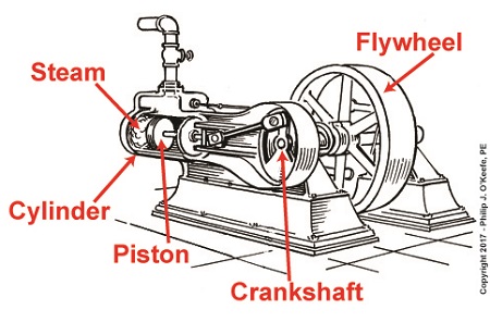
   Last time we had a look inside a marvelous piece of engineering machinery known as a crankshaft.   It plays a key role in converting the reciprocating linear motion of a steam driven engine into the rotary motion required to power externally mounted devices that are attached to it.   Today we’ll finish up our blog series on flywheels when we see how using one in conjunction with a crankshaft facilitates a more even transmission of energy.   Reciprocating engines maximize efficiency when they employ flywheels.

   We learned that the energy in the steam supply decreases as the piston moves in its cylinder, which means a concurrent decrease in the engine’s horsepower and its ability to power machinery.   Without an intervening action, the reciprocating steam engine would stall.   Now, let’s see how adding a flywheel to the crankshaft can solve the problem.

Reciprocating Engines Maximize Efficiency When They Employ Flywheels

Reciprocating Engines Maximize Efficiency When They Employ Flywheels


   As we’ve learned before, a flywheel stores up kinetic energy while the engine powering it is performing at full horsepower, but if that power should drop off or cease to be produced, the flywheel gives up the kinetic energy stored inside it so as to keep externally mounted machinery operating until that stored energy is exhausted.   This is all made possible because flywheels are designed to have moments of inertia sufficient to positively contribute to its storage of kinetic energy.   This inertia is a numerical representation of the flywheel’s resistance to change in motion.   Please review our past blog on the subject to refresh your memory.

   The overall effect is that while the engine is operating, there’s an even flow of energy between the engine and flywheel and horsepower is supplied to keep machinery mounted to the crankshaft operating.   Any diminishment in the power supplied will be compensated for by the flywheel’s stored kinetic energy.

   Next time we’ll introduce a new topic, a phenomenon known as cavitation.

opyright 2017 – Philip J. O’Keefe, PE

Engineering Expert Witness Blog

____________________________________


A Look Inside a Reciprocating Steam Engine

Wednesday, December 6th, 2017

    Last time we developed an engineering formula to calculate the horsepower required to accelerate a flywheel by way of a reciprocating steam engine, which contributes to the storage of kinetic energy inside a flywheel.   Today we’ll gain a clearer understanding of how this works when we take a look inside a reciprocating steam engine.

A Look Inside a Reciprocating Steam Engine

A Look Inside a Reciprocating Steam Engine


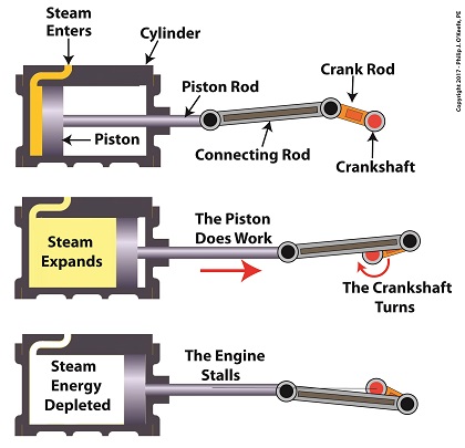
    A reciprocating steam engine performs the work of transforming steam’s heat energy into the mechanical energy needed to move a piston contained within a cylinder.   During a complete operating cycle this piston travels from one end of the cylinder to the other, then back again.   This is made possible because during the first half of the cycle pressurized steam enters one end of the cylinder and expands inside it, forcing the piston to move.

    This process inside the cylinder results in movement of a piston that’s attached to a piston rod, which in turn is connected to a crankshaft via a connecting rod and crank rod.   The crankshaft is a device which converts the reciprocating linear motion of an engine’s piston into rotary motion and in so doing facilitates the powering of any externally mounted rotating machinery attached to it.   So long as there’s ample steam to power the internal piston, over time, energy in the form of horsepower will be available to externally mounted devices.   The energy in the steam decreases as the steam expands behind the moving piston. So, the engine’s horsepower, will decrease as the piston travels to the end of the cylinder.   If the energy in the steam should become depleted, the reciprocating steam engine will stall. The engine will no longer be able to perform work.

    Next time we’ll see how a crankshaft works when we take a look inside it.

opyright 2017 – Philip J. O’Keefe, PE

Engineering Expert Witness Blog

____________________________________