Posts Tagged ‘steam turbine’
Wednesday, January 3rd, 2018
|
Shortly after I graduated with my engineering degree I worked as a power plant engineer at an electric utility. One day I was walking through the plant and heard a loud racket coming from the boiler feel pumps. These are the massive centrifugal pumps that deliver pressurized water to the boiler. The water is transformed into steam to drive steam turbines and spin electrical generators, which ultimately results in electrical power. The noise was so loud, it sounded like rocks were being ground up. I asked a coworker what was going on, and he replied matter-of-factly, “The pumps are cavitating.”
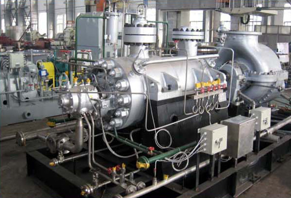
Boiler Feed Pumps Experience Cavitation
So what exactly is cavitation? We’ll find out next time when we explore the mechanics of this noisy phenomenon as it applies to boiler feed pumps and other centrifugal pumps.
opyright 2017 – Philip J. O’Keefe, PE
Engineering Expert Witness Blog
____________________________________ |
Tags: boiler, boiler feed pumps, cavitation, centrifugal pump, electric utility, electrical generator, engineering, power plant, steam turbine
Posted in Engineering and Science, Expert Witness, Forensic Engineering, Innovation and Intellectual Property, Personal Injury, power plant training, Product Liability | Comments Off on Boiler Feed Pumps Experience Cavitation
Wednesday, December 4th, 2013
|
Last time we ran our basic power plant steam turbine without a condenser. In that configuration the steam from the turbine exhaust was simply discharged to the surrounding atmosphere. Today we’ll connect it to a condenser to see how it improves the turbine’s efficiency.

As discussed in a previous blog, enthalpy h1 is solely dependent on the pressure and temperature at the turbine inlet. For purposes of today’s discussion, turbine inlet steam pressure and temperature will remain as last time, with values of 2,000 lbs PSI and 1000°F respectively, and calculations today will be based upon those values. So to review, the inlet enthalpy h1 is,
h1 = 1474 BTU/lb
If the condenser vacuum exists at a pressure of 0.6 PSI, a realistic value for a power plant condenser, then referring to the steam tables in the Van Wylen and Sonntag thermodynamics book, we find that the enthalpy h2 will be,
h2 = 847 BTU/lb
and the amount of useful work that the turbine can perform with the condenser in place would therefore be,
W = h1 – h2 = 1474 BTU/lb – 847 BTU/lb = 627 BTU/lb
So essentially with the condenser present, the work of the turbine is increased by 168 BTU/lb (627 BTU/lb – 459 BTU/lb). To put this increase into terms we can relate to, consider this. Suppose there’s one million pounds of steam flowing through the turbine each hour. Knowing this, the turbine power increase, P, is calculated to be,
P = (168 BTU/lb) ´ (1,000,000 lb/hr) = 168,000,000 BTU/hr
Now according to Marks’ Standard Handbook for Mechanical Engineers, a popular general reference book in mechanical engineering circles, one BTU per hour is equivalent to 0.000393 horsepower, or HP. So converting turbine power, P, to horsepower, HP, we get,
P = (168,000,000 BTU/hr) ´ (0.000393 HP/BTU/hr) = 66,025 HP
A typical automobile has a 120 HP engine, so this equation tells us that the turbine horsepower output was increased a great deal simply by adding a condenser to the turbine exhaust. In fact, it was increased to the tune of the power behind approximately 550 cars!
What all this means is that the stronger the vacuum within the condenser, the greater the difference between h1 and h2 will be. This results in increased turbine efficiency and work output, as evidenced by the greater numeric value for W. Put another way, the turbine’s increased efficiency is a direct result of the condenser’s vacuum forming action and its recapturing of the steam that would otherwise escape from the turbine’s exhaust into the atmosphere.
This wraps up our series on the power plant water-to-steam cycle. Next time we’ll use the power of 3D animation to turn a static 2D image of a centrifugal clutch into a moving portrayal to see how it works.
________________________________________
|
Tags: automobile engine, BTU, BTU/lb, coal power plant, energy, engineering expert witness, enthalpy, forensic engineer, horsepower, mechanical engineer, power, power engineer, power industry expert, power plant efficiency, power plant expert, power plant training instructor, power plant training seminars, steam pressure, steam turbine, steam turbine expert witness, steam water cycle, thermodynamics, vacuum, work
Posted in Engineering and Science, Expert Witness, Forensic Engineering, Innovation and Intellectual Property, Personal Injury, power plant training, Product Liability, Professional Malpractice | Comments Off on How Condensers Increase Efficiency Inside Power Plants
Tuesday, November 26th, 2013
|
Last time we learned that the amount of useful work, W, that a steam turbine performs is calculated by taking the difference between the enthalpy of the steam entering and then leaving the turbine. And in an earlier blog we learned that a vacuum is created in the condenser when condensate is formed. This vacuum acts to lower the pressure of turbine exhaust, and in so doing also lowers the enthalpy of the exhaust steam. Putting these facts together we are able to generate data which demonstrates how the condenser increases the amount of work produced by the turbine.
To better gauge the effects of a condenser, let’s look at the differences between its being present and not present. Let’s first take a look at how much work is produced by a steam turbine without a condenser.

The steam entering the turbine inlet has a pressure of 2000 pounds per square inch (PSI) and a temperature of 1000°F. Knowing these turbine inlet conditions, we can go to the steam tables in any thermodynamics book to find the enthalpy, h1. Titles such as Fundamentals of Classical Thermodynamics by Gordon J. Van Wylen and Richard E. Sonntag list enthalpy values over a wide range of temperatures and pressures. For our example this volume tells us that,
h1 = 1474 BTU/lb
where BTU stands for British Thermal Units, a unit of measurement used to quantify the energy contained within steam or water, in our case the water to steam cycle inside a power plant. Technically speaking, a BTU is the amount of heat energy required to raise the temperature of one pound of water by one degree Fahrenheit. The term lb should be a familiar one, it’s the standard abbreviation used for pound, so enthalpy is the measurement of the amount of energy per pound of steam flowing through, in this case, the turbine.
Since there is no condenser attached to the steam turbine’s exhaust in our illustration, the turbine discharges its spent steam into the surrounding atmosphere. The atmosphere in our scenario exists at 14.7 PSI because our power plant happens to be at sea level. Knowing these facts, the steam tables inform us that the value of the exhausted steam’s enthalpy, h2, is:
h2 = 1015 BTU/lb
Combining the two equations we are able to calculate the useful work the turbine is able to perform as:
W = h1 – h2 = 1474 BTU/lb – 1015 BTU/lb = 459 BTU/lb
This equation tells us that for every pound of steam flowing through it, the turbine converts 459 BTUs of the steam’s heat energy into mechanical energy to run the electrical generator.
Next week we’ll connect a condenser to the steam turbine to see how its efficiency can be improved.
________________________________________
|
Tags: British Thermal Unit, BTU, coal power plant expert, condensate, condenser, engineering expert witness, enthalpy, power engineer, power plant training seminar, pressure, steam, steam power plant, steam tables, steam turbine, steam turbine engineering expert witness, thermodynamics, turbine exhaust steam, vacuum, water, work
Posted in Engineering and Science, Expert Witness, Forensic Engineering, Innovation and Intellectual Property, Personal Injury, power plant training, Product Liability | Comments Off on Enthalpy Values in the Absence of a Condenser
Monday, November 18th, 2013
|
Last time we learned how enthalpy is used to measure heat energy contained in the steam inside a power plant. The higher the steam pressure, the higher the enthalpy, and vice versa, and we touched upon the concept of work, or the potential for a useful outcome of a process. Today we’ll see how to get the maximum work out of a steam turbine by attaching a condenser at the point of its exhaust and making the most of the vacuum that exists within its condenser.
Let’s revisit the equation introduced last time, which allows us to determine the amount of useful work output:
W = h1 – h2
Applied to a power plant’s water-to-steam cycle, enthalpy h1 is solely dependent on the pressure and temperature of steam entering the turbine from the boiler and superheater, as contained within the purple dashed line in the diagram below.

As for enthalpy h2, it’s solely dependent on the pressure and temperature of steam within the condenser portion of the water-to-steam cycle, as shown by the blue dashed circle of the diagram.
Next week we’ll see how the condenser, and more specifically the vacuum inside of it, sets the platform for increased energy production, a/k/a work.
________________________________________
|
Tags: boiler, coal power plant expert witness, condensate, condenser, electric generator, electric utility power plant expert, energy, engineering expert witness, enthalpy, forensic engineering, power engineering expert witness, power plant equipment, power plant training, steam pressure, steam temperature, steam turbine, superheater, turbine exhaust, turbine generator, vacuum, water-to-steam cycle, work
Posted in Engineering and Science, Expert Witness, Forensic Engineering, Innovation and Intellectual Property, Personal Injury, power plant training, Product Liability | Comments Off on Enthalpy and the Potential for More Work
Thursday, November 14th, 2013
|
Last time we learned how the formation of condensate within a power plant’s turbine results in a vacuum being created. This vacuum plays a key role in increasing steam turbine efficiency because it affects a property known as enthalpy, a term used to denote total heat energy contained within a substance. For the purposes of our discussion, that would be the heat energy contained within steam which flows through the turbine in a power plant.
The term enthalpy was first introduced by scientists within the context of the science of thermodynamics sometime in the early 20th Century. As discussed in a previous blog article, thermodynamics is the science that deals with heat and work present within processes. Enthalpy is a key factor in thermodynamics, and is commonly represented in engineering calculations by the letter h and denoted as,
h = u + Pv
where u is the internal energy of a substance, let’s say steam; P is the pressure acting upon a specific volume, v, of the steam; and P and v are multiplied together. Pressure is force per unit area and is measured in psi, pounds per square inch. For the purposes of our discussion, it’s the amount of pressure that steam places on pipes containing it.
Looking at the equation above, simple math tells us that if we increase the pressure, P, the result will be an increase in enthalpy h. If we decrease P, the result will be a decrease in h. Now, let’s see why this property is important with regard to the operation of a steam turbine.
When it comes to steam turbines, thermodynamics tells us that the amount of work they perform is proportional to the difference between the enthalpy of the steam entering the turbine and the enthalpy of the steam at the turbine’s exhaust. What is meant by work is the act of driving the electrical generator, which in turn provides electric power. In other words, the work leads to a useful outcome. This relationship is represented by the following equation,
W = h1 – h2
In terms of the illustration below, W stands for work, or potential for useful outcome of the turbine/generator process in the form of electricity, h1 is the enthalpy of the steam entering the inlet of the turbine from the superheater, and h2 is the enthalpy of the steam leaving at the turbine exhaust.

We’ll discuss the importance of enthalpy in more detail next week, when we’ll apply the concept to the work output of a steam turbine.
________________________________________
|
Tags: boiler, coal power plant, condensate, condenser, electrical generator, engineering expert witness, enthalpy difference, forensic engineer, heat energy, internal energy of steam, pipes, power plant design, power plant engineering expert, power plant operation, power plant training, pressure, specific volume of steam, steam pressure, steam turbine, steam turbine work, steam water cycle, superheater, thermodynamics, useful work, vacuum
Posted in Engineering and Science, Expert Witness, Forensic Engineering, Innovation and Intellectual Property, Personal Injury, power plant training, Product Liability | Comments Off on Enthalpy and Steam Turbines
Monday, October 28th, 2013
|
Last time we learned how the condenser recycles steam from the turbine exhaust by condensing it back into water for its reuse within the power plant steam-water cycle. This water is known as condensate, and after leaving the boiler feed pump at high pressure, it’s known as boiler feed water. Today we’ll introduce a special valve into the system, whose job it is to perform the important function of compensating for lost water. It’s known as the make-up valve.

The illustration shows the flow of steam and water within the cycle. Tracing the path of orange arrows will reveal it as a closed system.
Under ideal operating conditions recycled condensate from the condenser would provide enough water to keep the boiler indefinitely supplied. In reality water and steam leaks are a chronic problem within power plants, even when well maintained. Leaks typically occur due to worn parts on equipment, a condition which is commonly present due to the demanding operating conditions they must endure. First, there is the strain of continuous operation, then there are the high temperatures, typically greater than 1000°F, and high pressures that pipes, valves, pumps, and the boiler itself must endure. We’re talking about pressure higher than 2000 psi, that is, pounds per square inch. As a result, water levels within the boiler must periodically be replenished.
While tracing the arrows through the diagram, you would have come across the new make-up valve under discussion. It’s located on the pipe leading from the power plant’s water treatment system to the boiler feed pump. It’s normally kept closed, except under two circumstances, when the boiler is initially filled at startup, or when water replenishment needs to take place.
Due to water loss and difficult operating conditions, maintenance within the water-to-steam system of a power plant is a never ending task. There are miles of pipe connected to hundreds of pieces of equipment, all of which are distributed through a huge power plant structure. So the reality is that power plants operate with a continuous eye on leakage.
To contend with the leaks, human intervention is often required in the way of a boiler operator. Their job is to manually open the make-up valve to admit a fresh supply of water from the treatment plant to the boiler via the boiler feed pump. Once the system’s water requirements are replenished, the valve is once again closed.
Next time we’ll continue this series by discussing how the condenser enables the steam turbine to run more efficiently by creating a vacuum at the turbine’s exhaust.
________________________________________
|
Tags: boiler, boiler feed pump, closed system, coal-fired power plant, condensate, condenser, electric utility power plant, engineering expert witness, feed water, forensic engineer, high pressure, high temperature, make up valve, pipe, power engineer, power plant, power plant engineering expert witness, power plant maintenance, power plant operation, power plant training, pumps, start up, steam leaks, steam turbine, steam water cycle, turbine exhaust, vacuum, valves, water leaks, water to steam system, water treatment system
Posted in Engineering and Science, Expert Witness, Forensic Engineering, Innovation and Intellectual Property, Personal Injury, power plant training, Product Liability | Comments Off on The Make-up Valve in the Power Plant Steam to Water Cycle
Monday, October 14th, 2013
|
We’ve been discussing various aspects of a power plant’s water-to-steam cycle, from machinery specifics to identifying inefficiencies, and today we’ll do more of the same by introducing the condenser hot well and discussing its importance as a key contributor to the conservation of energy, specifically heat energy. Let’s start by returning our attention to the steam inside the condenser vessel.
Last week we traced the path of the condenser’s tubes and learned that the cool water contained within them serve to regulate the steam’s temperature surrounding them so that temperatures don’t rise dangerously high. To fully understand the important result of this dynamic we have to revisit the concept of latent heat energy explored in a previous article. More specifically, how this energy factors into the transformation of water into steam and vice versa.
Steam entering the condenser from the steam turbine contains latent heat energy that was added earlier in the water/steam cycle by the boiler. This steam enters the condenser just above the boiling point of water, and it will give up all of its latent heat energy due to its attraction to the cool water inside the condenser tubes. This initiates the process of condensation, and water droplets form on the exterior surfaces of the tubes.

The water droplets fall like rain from the tube surfaces into the hot well situated at the bottom of the condenser. This hot well is essentially a large basin that serves as a collection point for the condensed water, otherwise known as condensate.
It’s important to collect the condensate in the hot well and not just empty it back into the lake, because condensate is water that has already undergone the process of purification. It’s been made to pass through a water treatment plant prior to being put to use in the boiler, and that purified water took both time and energy to create. The purified condensate also contains a lot of sensible heat energy which was added by the boiler to raise the water temperature to boiling point, as we learned in another previous article. This heat energy was produced by the burning of expensive fuels, such as coal, oil, or natural gas.
So it’s clear that the condensate collecting in the hot well has already had a lot of energy put into it, energy we don’t want to lose, and that’s why its an integral part of the water-to-steam setup. It acts as a reservoir, and the drain in its bottom allows the condensate to flow from the condenser, then follow a path to the boiler, where it will be recycled and put to renewed use within the power plant.
Next week we’ll follow that path to see how the condensate’s residual heat energy is put to good use.
________________________________________ |
Tags: boiler, boiling point, coal, coal fired boiler, condensate, condensed water, condenser, drain, electric utility power plant, engineering expert witness, forensic engineer, fuel, heat energy, hot well, latent heat energy, licensed professional engineer, machinery, mechanical engineer, natural gas, oil, power engineer, power plant engineer, power plant training seminars, purified water, residual heat energy, sensible heat energy, steam turbine, water droplets, water temperature, water treatment plant, water-to-steam cycle
Posted in Engineering and Science, Expert Witness, Forensic Engineering, Innovation and Intellectual Property, Personal Injury, power plant training, Product Liability | Comments Off on How A Power Plant Condenser Works, Part 3
Sunday, October 6th, 2013
|
Winter is fast approaching. Imagine living in a house without insulation. Now imagine your heating bill, which will be high due to the tremendous amount of heat loss. Energy is a precious resource, no matter how it’s produced, and its conservation within a power plant’s steam/water cycle is of vital importance.
Last time we learned about the transfer of heat energy within a power plant’s condenser, where some of the heat energy contained within its steam is absorbed by the cool lake water contained inside its tubes.

Steam is continuously flowing into the condenser from the steam turbine, so it’s essential for the circulating pump to keep a fresh supply of lake water flowing through the condenser’s tubes in an effort to keep temperatures under control.
The compensating action that’s provided by the cool lake water flowing within the tubes, represented by green arrows in the illustration, keeps the temperature inside the tubes from rising and becoming equal to the steam’s temperature outside of them. If the flow of cool water through the tubes were to stop and the temperatures inside and outside the tubes become equal, the water contained inside the tubes would boil off to steam, resulting in the tubes bursting and a wrecked condenser.
After absorbing heat energy from the surrounding steam, the warmed lake water within the tubes follows a circuitous path through the tubing, eventually emptying out into the lake. The orange arrows in the illustration show this path.
Okay, with this warm water entering the lake, doesn’t that harm the eco system? Actually its impact is negligible. You see, the temperature of the lake water leaving the condenser is only about 10°F higher than when it was pumped from the lake. Add this to the fact that the volume of water contained within a lake is huge in comparison to the small amount of warmed water being returned to it.
Next week we’ll see how the loss of heat energy affects the steam, and how an important part of the condenser known as the hot well comes into play.
________________________________________ |
Tags: coal power plant, coal power plant engineering, condenser, condenser circulating pump, condenser tubes, condenser vessel, cooling water, electric utility power plant training, expert witness, forensic engineer, heat energy, lake water, steam turbine, thermal engineering, turbine exhaust steam
Posted in Engineering and Science, Expert Witness, Forensic Engineering, Innovation and Intellectual Property, Personal Injury, power plant training, Product Liability | Comments Off on How A Power Plant Condenser Works, Part 2
Wednesday, October 2nd, 2013
|
Last time we began our discussion on power plant inefficiencies and indentified a major contributor, the heat energy dispelled into the atmosphere through the turbine exhaust. Today we’ll see how a piece of equipment known as the condenser comes into play to deal with this problem. Let’s see how it works.
First, water from our plant’s water source, say a nearby lake, is siphoned into the condenser circulating pump, which delivers it to the condenser. This lake water path appears in yellow. You’ll notice that the lake water follows a circuitous path from the lake, through the condenser circulating pump, then the condenser tubes, until finally it is returned to the lake.
Now the cool lake water, denoted by green arrows, is made to pass through the condenser’s many tubes, while steam from the turbine exhaust surrounds them. The tubes keep the lake water segregated from the cloud of steam surrounding them inside the condenser vessel. In other words, the lake water’s path is a closed system, never coming into direct physical contact with the surrounding steam.
What’s happening inside our condenser is demonstrative of a fundamental principle of thermal engineering, that is, that hot will travel in the direction of cold. More specifically, within our condenser the heat energy in the steam cloud surrounding the condenser tubes will be attracted to the cool lake water contained within the tubes. This causes the heat energy contained within the steam to leave it, and get absorbed by the cool lake water flowing within the tubes.
We’ll begin to find out how these dynamics influence what’s happening with our water-to-steam power plant cycle next time.
________________________________________ |
Tags: coal power plant, coal power plant engineering, condenser, condenser circulating pump, condenser tubes, condenser vessel, cooling water, electric utility power plant training, expert witness, forensic engineer, heat energy, lake water, steam turbine, thermal engineering, turbine exhaust steam
Posted in Engineering and Science, Expert Witness, Forensic Engineering, Innovation and Intellectual Property, Personal Injury, power plant training, Product Liability | Comments Off on How A Power Plant Condenser Works, Part 1
Sunday, September 22nd, 2013
|
Last week we identified some inefficiencies in our water to steam power plant energy cycle. The superheater addressed some of these concerns, but not others. Our illustration discloses one of these wasteful areas to be coming from the turbine exhaust. That’s energy laden steam being expelled into the surrounding atmosphere! It’s the same heat energy that was produced in the boiler when water was transformed into steam. It came from burning fuels like coal, natural gas, and oil, all expensive and precious natural resources.

In its present configuration the power plant will work, but because steam is being continually dispersed into the atmosphere, it must continually be replenished. The key ingredient, water, must be drawn into the power plant from a nearby source, treated for contaminants, then fed into the boiler to make up for lost steam. That wastes both water and energy, because the make-up pump, which draws water from the lake for treatment, (thus “making up” for spent water), is continuously operating, resulting in excessive wear and tear and increased operating costs.
Fortunately, power plant engineers have devised methods to correct these inefficiencies. They’ve come up with a clever means of recapturing exhaust steam, thus enabling it to recycle within the system. Next week we’ll see how this is accomplished with a piece of equipment called a condenser.
________________________________________ |
Tags: burning fuel, coal, coal power plant training, condenser, contaminants, electric utility engineer, energy cycle, engineering expert witness, exhaust steam, forensic engineer, fuel, heat, heat energy, makeup water pump, natural gas, oil, operating costs, power engineer, power plant inefficiency, steam power plant, steam turbine, water treatment
Posted in Engineering and Science, Expert Witness, Forensic Engineering, Innovation and Intellectual Property, Personal Injury, power plant training, Product Liability | Comments Off on Power Plant Inefficiency


