| My journey through engineering school was marked by a cast of colorful characters from around the world. I remember one Russian professor in particular, fond of extolling the virtues of Russian engineering by the statement, “In Soviet Union steel ingots roll in one door, military tanks roll out other door.” During that period of history in his homeland, it was not uncommon for all components down to the smallest screw to be manufactured within the same factory.
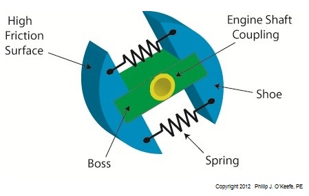
That professor taught me all about clutch mechanisms, and whether they’re present in Soviet tanks or grass trimmers they perform the same basic function. Let’s take a look at one now. Figure 1
Figure l shows my color-enhanced clutch illustration, which makes it easy to identify the different components of a centrifugal clutch. The main part of the clutch is colored green and it’s respectfully referred to as the “boss.” I assume it’s earned the title due to its role in keeping all component parts of the clutch assembly together. The blue portion shows two clutch shoes. The boss fits loosely into notches within the shoes. The curved surfaces on the shoes are composed of a high friction material, and we’ll see why later. Two springs attached to the shoes cause them to pull towards each other and keep them from falling off the ends of the boss. The yellow portion shows the engine shaft coupling. It’s permanently affixed to the center of the boss. This coupling has a hole in it that enables the clutch mechanism to be attached onto an engine shaft with a threaded nut or some other type of mechanical fastener. Now that we’re familiar with a centrifugal clutch’s parts we can see how they come into play in a real world application, that of an engine shaft. We’ll explore that next week. ____________________________________________
|
Engineering Expert Witness Blog
Published by Philip J. O'Keefe, PE, MLE


