|
Last week we worked with a gear train equation and found that the gears under consideration were not sized properly to run a lathe. Today we’ll increase the gear train torque and solve that problem. How do we manipulate things to obtain the 275 inch pounds of torque required to drive the lathe? Last week we tried using a driven gear with a diameter of 8 inches and found that to be insufficient in size. So today the first thing we’ll try is a bigger driven gear, one with a pitch diameter of 8.5 inches. That’s 0.5 inches larger in diameter than the gear used in last week’s equation, and this just so happens to be the next size up in the gear manufacturer’s catalog. As we did last week, we’ll begin our calculations with the torque ratio equation: T1 ÷ T2 = D1 ÷ D2 We’ll use the same values as last week for T1, and D1, 200 inch pounds and 3 inches respectively, but we’ll increase the new value for D2, the driven gear pitch radius, to 4.25 inches (the new pitch diameter divided by two). Inserting these values into the torque equation, the only variable remaining without a value is torque T2. Let’s determine that value now by using algebra to rearrange terms. (200 inch pounds) ÷ T2 = (3 inches) ÷ (4.25 inches) (200 inch pounds) ÷ T2 = 0.70 T2 = (200 inch pounds) ÷ (0.70) = 283.33 inch pounds The value of T2 is found to be 283.33 inch pounds, which meets the torque requirement required to run the lathe. We were able to arrive at this torque by simply increasing the size of the driven gear relative to the size of the driving gear. In the world of Newtonian physics, this is a rather straightforward arrangement. It all boils down to this simple dynamic: When the motor’s force is acting upon a wider gear, the force is located a longer distance from the center of the driving gear shaft, which results in more torque on the shaft. As borne out by the example provided today, the larger the driven gear is in comparison to the driving gear, the more the gear train amplifies the torque that’s delivered by the motor. The principle at play here is exactly the same as that presented in a previous blog article where, for a given force exerted upon a wrench, torque was increased by simply increasing the length of the wrench handle. Some of you may be wondering why we didn’t just use a bigger, more powerful motor to begin with, thereby eliminating the need for a gear train and all the calculations we’ve been running? We’ll see why that’s not always possible or practical next time. _______________________________________
|
Posts Tagged ‘torque converter’
How to Increase Gear Train Torque
Thursday, July 10th, 2014The Methodology Behind Gear Train Torque Conversions
Sunday, June 22nd, 2014|
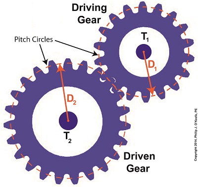
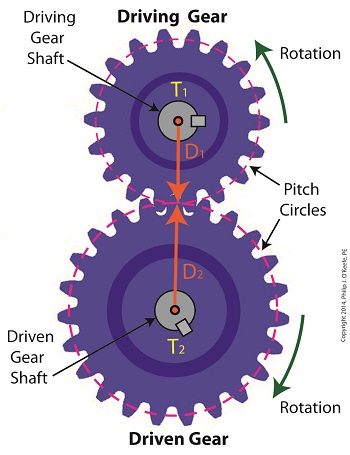
Last time we learned that gear trains are torque converters, and we developed a torque ratio equation which mathematically ties the two gears in a gear train together. That equation is: T1 ÷ T2 = D1 ÷ D2 Engineers typically use this equation knowing only the value for T2, the torque required to properly drive a piece of machinery. That knowledge is acquired through trial testing during the developmental phase of manufacturing. Once T2 is known, a stock motor is selected from a catalog with a torque value T1 which closely approximates that of the required torque, T2. Then calculations are performed and lab tests are run to determine the driving and driven gear sizes, D1 and D2 which will enable the gear train to convert T1 into the required value of T2. This series of operations are often a time consuming and complex process. To simplify things for the purpose of our example, we’ll say we’ve been provided with all values required for our equation, except one, the value of T2. In other words, we’ll be doing things in a somewhat reverse order, because our objective is simply to see how a gear train converts a known torque T1 into a higher torque T2. We’ll begin by considering the gear train illustration above. For our purposes it’s situated between an electric motor and the lathe it’s powering. The motor exerts a torque of 200 inch pounds upon the driving gear shaft of the lathe, a torque value that’s typical for a mid sized motor of about 5 horsepower. As-is, this motor is unable to properly drive the lathe, which is being used to cut steel bars. We know this because lab testing has shown that the lathe requires at least 275 inch pounds of torque in order to operate properly. Will the gears on our gear train be able to provide the required torque? We’ll find out next time when we insert values into our equation and run calculations. _______________________________________
|
Gear Trains Are Torque Converters and Why That’s Important
Friday, June 13th, 2014|
Today we’ll analyze the relationship between the sizes of the gears within a gear train, as well as their torques, and get an understanding of how gear trains act as torque converters. Last time we developed a single torque equation for a simple gear train: T1 ÷ D1 = T2 ÷ D2 (1) where T1 and T2 are the driving and driven gear torques, and D1 and D2 are the driving and driven gear pitch circle radii. The first thing to be done in order to arrive at a torque conversion analysis is group together like terms in equation (1) so that we end up with terms relating to torque on one side of the equation and terms relating to gear size on the other. We’ll use algebra to divide both sides of the equation by T2 , then multiply both sides by D1. After doing so we get, T1 ÷ T2 = D1 ÷ D2 (2) In equation (2), T1 ÷ T2 is a torque ratio. Ratio means we’re dividing one of the torques by the other. Likewise, D1 ÷ D2 is a gear pitch radius ratio, that is to say, it’s the ratio of one gear’s physical size relative to the physical size of the other. What equation (2) tells us is that the individual gears on the gear train will produce torque values which are dependent upon the physical sizes of the two gears with respect to one another. So what’s the practical significance of this? When gear trains are used in industrial applications, they always act as torque converters. One such example would be when a low-torque-producing electric motor is used to power a steel cutting lathe. If the motor isn’t tough enough to power the lathe, it itself won’t be modified, but the torque it produces will be. This modification is accomplished by converting the motor’s low torque value, T1, to a higher torque value, T2 , and it’s equation (2) that’s used to do it. Next time we’ll delve deeper into the methodology behind gear train torque conversions. _______________________________________
|


