|
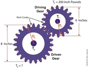
Last time we set up an example where an electric motor is connected to a lathe via a gear train. Today we’ll take the numerical values present on that gear train and plug them into the torque ratio equation we’ve been working with for the past few blogs. In the illustration below the electric motor exerts 200 inch pounds of torque upon the driving gear. The driving gear pitch circle diameter is 6 inches, while the driven gear pitch circle diameter is 8 inches. It’s been determined through previous lab testing that the lathe we’ll be using requires at least 275 inch pounds of torque to be exerted upon the driven gear shaft in order to operate properly. Will the gear train shown below meet this requirement? First, a review of the torque ratio equation: T1 ÷ T2 = D1 ÷ D2 Now we’ll crunch numbers. T1 is equal to 200 inch pounds, D1 is equal to 3 inches (pitch radius equals pitch diameter divided by two), and D2 is equal to 4 inches. This gives us: (200 inch pounds) ÷ T2 = (3 inches) ÷ (4 inches) T2 = (200 inch pounds) ÷ (0.75) = 266.67 inch pounds So, does the gear train as presented here supply enough torque to power the lathe properly? No, it does not. It provides only 266.67 inch pounds, not the 275 inch pounds of torque required. Next time we’ll see how to manipulate gear sizes within a gear train in order to meet a given torque requirement. _______________________________________
|
Engineering Expert Witness Blog
Published by Philip J. O'Keefe, PE, MLE


