|
Last time we learned how both low and high pressures exist within a single centrifugal pump, and if water pressure at the inlet is low enough, the cavitation process begins. Today we’ll see how these rapidly imploding water vapor bubbles create serious problems in the pump’s high pressure area.
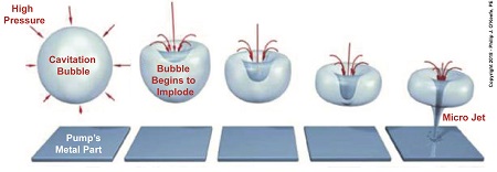
Rapidly Imploding Bubbles Create Problems
Water flows from low pressure at a centrifugal pump’s inlet to high pressure upstream when it meets up with the pump’s impeller. This high pressure causes cavitation bubbles formed at the inlet to rapidly implode, that is, collapse in on themselves. Implosion occurs because pressure outside the bubbles is much greater than the pressure inside them. This pressure difference exists because the bubbles were formed in the low pressure area of the pump. When cavitation bubbles meet up with high pressure areas deep inside the pump, they get squeezed hard and burst rapidly, creating multitudes of shock waves, grinding noise, and vibration so intense it sounds as though gravel, not steam bubbles, are passing through the pump. The noise and vibration are bad enough, but cavitation has far worse consequences. Rapidly imploding bubbles form tiny but powerful micro jets of water which hold an enormous amount of kinetic energy. When these jets hit the pump’s metal interior, their kinetic energy causes minute fragments of metal to break away. Over time these tiny water jets wear away enough metal to cause damage to the pump’s interior and interfere with function. Next time we’ll see how cavitation bubbles flowing through the low pressure area of a pump degrade its performance. opyright 2018 – Philip J. O’Keefe, PE Engineering Expert Witness Blog ____________________________________ |