| The world of electricity is full of mysteries and often unanticipated outcomes, and if you’ve been reading along with my blog series you have been able to appreciate and come to some understanding of a fair number of them. This week’s installment will be no exception.
Last week we looked briefly at the high voltage circuit within a microwave oven. We discovered that the circuit contains a transformer that raises 120 volts alternating current (AC) to a much higher voltage, around 4000 volts AC. The circuit then transforms the AC into direct current (DC) with the help of electronic components known as a diode and capacitor. Let’s take a closer look at how the diode and capacitor work together to make AC into DC. Let’s follow an AC wave with the aid of a device called an oscilloscope. An oscilloscope takes in an electronic signal, measures it, graphs it, and shows it on a display screen so you can see how the signal changes over time. An AC wave is shown in Figure 1 as it would appear on an oscilloscope. Figure 1 – Alternating Current Wave You can see that each wave cycle starts with a zero value, climbs to a positive maximum value, then back to zero, and finally back down to a maximum negative value. The current keeps alternating between positive and negative polarity, hence the name “alternating current.” Within the microwave oven’s high voltage circuitry the transformer does the job of changing, or transforming if you will, 120 volts AC into 4000 volts AC. This high voltage is needed to make electrons leave the cathode in the magnetron and move them towards the anode to generate microwaves. But we’re not done with the transformation process yet. The magnetron requires DC to operate, not AC. DC current remains constant over time, maintaining a consistent positive value as shown in Figure 2. It is this type of consistency that the magnetron needs to operate.
Figure 2 – Direct Current The microwave’s diode and capacitor work together to convert the 4000 volts AC into something which resembles 4000 volts DC. First the diode acts like a one-way valve, passing the flow of positive electric current and blocking the flow of negative current. It effectively chops off the negative part of the AC wave, leaving only positive peaks, as shown in Figure 3.
Figure 3 – The Diode Chops Off The Negative Part of the AC Wave Between the peaks are gaps where there is zero current, and this is when the capacitor comes into play. Capacitors are similar to batteries because they can be charged with electrical energy and then discharge that energy when needed. Unlike a battery, the capacitor charges and discharges very quickly, within a fraction of a second. Within the circuitry of a microwave oven the capacitor charges up at the top of each peak in Figure 3, then, when the current drops to zero inside the gaps the capacitor comes into play, discharging its electrical energy into the high voltage circuit. The result is an elimination of the zero current gaps. The capacitor acts as a reserve energy supply to fill in the gaps between the peaks and keep current continually flowing to the magnetron. We have now witnessed a mock DC current situation being created, and the result is shown in Figure 4.
Figure 4 – The Capacitor Discharges to Fill In The Gaps Between Peaks The output of this approximated DC current looks like a sawtooth pattern instead of the straight line of a true DC current shown in Figure 2. This ripple pattern is evidence of the “hoax” that has been played with the AC current. The net result is that the modified AC current, thanks to the introduction of the diode and energy storing capacitor, has made an effective enough approximation of DC current to allow our magnetron to get to work jostling electrons loose from the cathode and putting our microwave oven into action. You now have a basic understanding of how to turn AC into an effective approximation of DC current. Next week we’ll find out how this high voltage circuit can prove to be lethal, even when the microwave oven is unplugged. ____________________________________________ |
Posts Tagged ‘voltage’
The Microwave Oven — More on How AC Becomes DC
Monday, August 15th, 2011


Transformers – Electric Utility Power Savers
Sunday, January 2nd, 2011| Each day millions of Americans start their mornings with coffee, brewed in a coffee maker, and a microwaved breakfast. They flick on the light and exhaust fan before starting their showers and blow dry their hair afterwards. Each of these acts of modern living is a small miracle. And if you’re like most people you can’t see the power plant supplying the power to your modern conveniences from your home, and how the electricity travels from the plant to you isn’t too clear.
Truth is the process of supplying our homes with power isn’t as straightforward as you might think, and the actual transmission of that power isn’t straightforward at all. To begin with, the wires used in power lines are less than perfect conductors of electricity. Along any given length of wire there are all sorts of imperfections in the metal, and these tend to resist the flow of electrical current. These imperfections will always exist to some extent, even with the best manufacturing techniques and quality control, and the longer the power line, the more resistance the power flow will meet. The result is loss of electrical power. If there weren’t some kind of compensatory action at work to rectify this, your morning routine wouldn’t be nearly so smooth. To address the problem of power loss electric utilities use step-up transformers, similar to the one in Figure 1. This enables voltage produced by the generator at the plant to be raised to a higher voltage, in turn enabling it to travel longer distances and remain effective.
Figure 1 – Electricity Leaving the Power Plant Goes Through a Step-Up Transformer For example, let’s say that an electric generator puts out 12,000 volts, and a step-up transformer raises that to 765,000 volts, enabling transmission to customers far away. If you will recall from last week’s blog, with electrical transformers, there is an inverse relationship between voltage and current. So, when a step-up transformer increases input voltage, it actually results in a lowering of electrical current. So how does this phenomenon aid in power transmission? Simply put, when there is less current flowing through the wires, there is an accompanying reduction in power loss over the long length of the transmission line. Let’s take a look at what happens when the power reaches our homes. Figure 2 shows a simplified distribution route from the power plant. Figure 2 – A Step-Down Transformer is Used to Supply Electric Utility Customers First, the higher voltage originating from the step-up transformer at the power plant is decreased by the use of a step-down transformer located in a substation many miles away at the other end of the transmission line. The use of this intermediary step-down transformer effectively lowers the voltage and at the same time raises the current at the other end of the line, the end where customers like you and I are waiting to use our hair dryers unimpeded. The path that the power follows is somewhat circuitous, but well planned out, with numerous strategically positioned distribution lines acting as the final leg of delivery. These distribution lines do what their name implies, they weave their way along streets and alleys, finally distributing electricity to customers. A step-down transformer located in a substation along the power transmission route allows this all to happen. It can readily convert the 765,000 volts being sent by the power plant to the 25,000 volts needed to feed distribution power lines. These, in turn, power individual homes, hospitals, etc. Now you obviously can’t plug a television into a 25,000 volt wall outlet located in your house, so another step-down transformer is required to temper it into power that’s both usable and safe. The one in our diagram is mounted on a nearby utility pole, and its job is to lower the 25,000 volts which it receives into a more manageable 240 and 120 volts, which is then fed into your home. That wraps up our series on electrical transformers. Perhaps the next time you flip that switch in your home, whether it be on your hair dryer, TV, or what have you, you’ll pause for a moment to reflect on the long path it has followed to make your life just a little bit easier. _____________________________________________
|

Transformers – The Voltage/Current Trade-Off
Sunday, December 26th, 2010|
As a child I considered the reindeer Rudolph, with his nose so bright, to be a marvel of engineering. Now an adult, I remain perplexed as to the mystery behind the self-generating power source behind his nose. Did it ever overheat? I wondered. Perhaps today’s discussion can shed some light on the matter. During the course of our discussion of electricity certain terms have been tossed about, like voltage and current. For some the distinction between the two may be unclear, and that is what we’ll be addressing today. Electricity is a rather abstract phenomenon, but you may consider the flow of electrical current through a wire to be much like water flowing through a garden hose. The water won’t flow unless there’s sufficient pressure behind it, and that pressure is supplied by pumps, either at your city water works or your personal well. Take away the pressure, and the water stops flowing through the hose. Electricity flows in much the same manner. It requires a pushing pressure to get it on its journey from power plant to home, and that pressure is voltage. Take away voltage, and the current stops flowing through the wire. Voltage is, of course, produced by an electrical generator at the power plant. Last time we saw how an electrical transformer can reduce high voltage to low voltage and how this process also works in reverse. But how can that be? How can low voltage be turned into high? Is it really possible to get “something from nothing”? Let’s take a closer look. When a light bulb burns out in your home, you routinely look at the bulb to see how many watts it is so you can replace it with the same type. But what exactly is a “watt”? It’s a unit of power, and the markings on the bulb tell you how much electrical power it consumes when you use it. Generally speaking, this electrical power is related to voltage and current by this formula: Power = Volts × Electrical Current Knowing this, if I have a 60 watt bulb in a table lamp, and I plug it into a 120 volt wall outlet, then how much electrical current is the lamp going to draw from the outlet? Using the formula above and a little algebra, we get: Electrical Current = Power ÷ Volts Electrical Current = 60 watts ÷ 120 volts = 0.5 amperes And believe it or not, this same formula that’s used to assess power of a light bulb also applies to electrical transformers. Basically, the power going into the transformer is equal to the power coming out. To see how this works, consider the example step-up transformer shown in Figure 1, which converts a low voltage to a higher one. By the way, “step up” transformers have all sorts of applications. For example, they are used by electric utilities to raise the voltage produced by a power plant to make it more economical to transmit to far away customers. We’ll get into that in another article.
Figure 1 – A Step-Up Transformer In this example the input voltage on the primary coil is stepped up from 120 volts to 480 volts on the secondary coil, and this works according to the formula we learned about in last week’s blog: NP ÷ NS = VP ÷ VS where NP and NS are the number of turns of wire in the primary and secondary coils respectively, and VP and VS are the voltages of the primary and secondary coils respectively. Plugging in the numbers we get: 50 turns ÷ 200 turns = 120 volts ÷ VS [(200 turns ÷ 50 turns) × 120 volts] = VS = 480 volts Okay, for the sake of our example let’s say that an electric motor is connected to the 480 volt secondary coil. We have an electric meter hooked up to the primary coil and we measure a 2 ampere (a.k.a. “amps”) electrical current flowing through it. Without having the benefit of another electric meter positioned at the secondary coil, how can we measure how much electrical current is flowing through it? The current flowing through the secondary coil is found by equalizing the power in the primary and secondary coils: PowerP = PowerS Another way of stating this is to say that electrical power is equal to volts times current, so the equation becomes: VP × IP = VS × IS where IP and IS are the primary coil and secondary coil currents, respectively. Plugging in the numbers and working a little algebra we get the electrical current in the secondary coil: 120 volts × 2 amps = 480 volts × IS IS = (120 volts × 2 amps) ÷ 480 volts = 0.5 amps This shows us that the current flowing in the secondary coil is lower than that of the primary coil. It is therefore obvious that the voltage increase in the secondary coil comes at the expense of electrical current that can flow through the secondary coil. Squeeze down on current, voltage goes up. Squeeze down on voltage, current goes up. The power flowing through the transformer stays the same. Conversely, step-down transformers reduce the voltage coming in, and thereby produce the reverse effect. There is an actual increase in current that can flow through the secondary coil. This principle exemplifies the tradeoff process which is often present in science and engineering. Next time we’ll explore how both step-up and step-down transformers are used by electric utilities to transmit power from power plants to its customers tied into the utility grid. As for Rudolph and his power source, that’s still under investigation. _____________________________________________
|

Transformers and The Magic of Electricity
Sunday, December 5th, 2010| No, the next series of articles is not about those talking, morphing, gigantic killing machines that children love to play with. We’re going to talk about the type that adults just can’t live without.
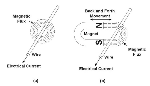
You’ve probably heard the term “electrical transformer” at some point, but you may not be entirely sure what is meant by it. Most don’t realize that they use them all the time, like when they recharge their cell phone battery. That little black box that plugs into the wall outlet is one of them, and what they do is perform the important task of reducing the 120 volts of power that fuels your home’s outlets down to a lower voltage level, for example, 12 volts, which can be used by small electronic devices. But before I explain how this reduction process works we need to understand magnets. Magnets, those wonderful curiosities that mesmerized you as a kid, keeping you busy for hours picking up nails and paper clips, have many practical applications, although they weren’t considered to be anything more than amusing novelties until the early 19th Century. That’s when a French scientist by the name of André-Marie Ampére studied the relationship between magnetism and electricity. What he found was that when an electrical current is run through a wire it turns into a magnet. Ampere’s work was then built upon by British scientist Michael Faraday. He discovered that electric current passing through wire creates magnetic lines of flux that encircle the wire as shown in Figure 1 (a). Faraday also discovered that if you move a magnet back and forth near a wire, as shown in Figure 1 (b), you can generate an electrical current in the wire.
Figure 1 – Relationships Between Electricity and Magnetism Why does this happen? Well, magnets work as they do because they have a magnetic north (N) and south (S) pole, and lines of magnetic flux extend from one pole to the other. You can actually see these lines of flux if you sprinkle iron filings between the poles. The iron filings are attracted to the magnet and align themselves along the lines as shown in Figure 2. When the lines of flux move through the wire, they induce an electrical current in it. As long as you keep the magnet moving back and forth, lines of flux will continue to pass through the wire, and the current will keep flowing. When the magnet stops moving, the current in the wire also stops.
Figure 2 – Iron Filings Aligned Along Lines of Magnetic Flux Faraday soon began experimenting with coiled wires and iron rods. He wanted to see how electrical current flowing through one coiled wire would affect another coiled wire in close proximity. His basic experimental setup is shown in Figure 3.
Figure 3 – Michael Faraday’s Experiment Faraday’s experiment consisted of two insulated wires, each coiled around an iron rod. The first coiled wire ran to a battery and then a switch. The switch enabled Faraday to connect and disconnect the battery to the first coil during his experiments. The second coiled wire was connected to an instrument called a Galvanometer, which measures the amount of electricity flowing through the wire. When the switch was closed, connecting the first coil to the battery, Faraday noticed that the Galvanometer’s indicator needle moved, then returned to zero. Somehow the electricity flowing from the battery to the first coil was causing an electric current to momentarily flow in the second coil. But how does electricity flow from one coil to the other if they’re not connected? It doesn’t. What’s actually taking place is known as “electromagnetic induction.” Faraday’s experiment enabled him to conclude that current flowing through the first coil set up lines of magnetic flux in the iron rod to which both coiled wires were attached. When the switch was closed, the lines of magnetic flux built in intensity until they induced a current in the second coil. But when the magnetic flux reached its full intensity, and stayed at full intensity, the current induced in the second coil stopped flowing. Faraday’s initial confusion as to the state of affairs soon changed into the Eureka! moment of discovery, and he was able to conclude that current will flow in the second coil only if the lines of magnetic flux are fluctuating in intensity. Next week we’ll see how an as yet undiscovered young inventor used the results of Faraday’s experiment to build the first electrical transformer. _____________________________________________ |


