|
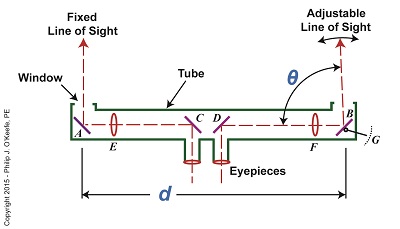
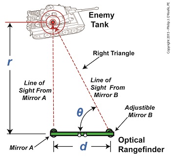
Last time we covered the mirrors found inside an optical rangefinder. Today we’ll discuss its other components, magnifying lenses E and F and the indicator gauge, G. See Figure 1. Figure 1 Magnifying lenses E and F are positioned in such a way that the two horizontal lines of sight reflecting off mirrors C and D pass through them on their way to mirrors A and B. Lenses E and F are adjustable, allowing the viewer to manipulate them until the distant image being viewed is seen in clear focus through both eyepieces, just as would happen with binoculars. To see the rangefinder in action let’s go out to the battlefield, where it’s routinely used. A soldier notices an enemy tank off in the distance. To make an accurate hit with his artillery he must determine the distance r from his position to the tank. The soldier in charge of this task observes the tank through the rangefinder’s eyepieces and manually adjusts lenses E and F until it comes into focus. He then adjusts the rangefinder’s mirror B until the line of sight extending from it converges on the tank along with the fixed line of sight from mirror A as shown in Figure 2. When the two images converge a right triangle is formed, and as we learned in a previous article, this fact will enable us to calculate r by using trigonometry with this formula: r = d × tan(θ) We already know that the value of d, the distance between mirrors A and B, is three feet. All that is left to be determined is the angle θ that’s formed between adjustable mirror B‘s forward line of sight out the tube’s opening and the horizontal line of sight between D and B. The last component within an optical rangefinder to be discussed is the indicator gauge, notated as G in Figure 1. This gauge is attached to mirror B inside the tube and is used to measure the angle θ that’s produced as the mirror is adjusted. When the lines of sight from mirrors A and B converge and the tank comes into clear view through the eyepieces, the value of θ can be read on the gauge’s numerical graduated scale, which is located on the exterior of the tube. Next time we’ll see how trigonometry and the study of right triangles prove indispensable when measuring distances with an optical rangefinder. ____________________________________
|
Engineering Expert Witness Blog
Published by Philip J. O'Keefe, PE, MLE


