| Believe it or not as a kid in grade school I used to hate math, particularly algebra. None of my teachers were able to decipher its complexities and render it comprehensible to me or the majority of my classmates. Then in high school everything changed. I had Mr. Coleman for freshman algebra, and he had a way of making it both understandable and fun, in a challenging kind of way. With 40 years of teaching under his belt, Mr. Coleman knew exactly how to convey the required information in an understandable manner, and to this day I find his insights useful in solving engineering calculations.
Last time we began our discussion on Ohm’s Law and how it may be applied to our example circuit to solve for the electrical current flowing through it. Let’s continue our discussion to see how the Law applies to only one part of the circuit. Then, we’ll use a little algebra to show how the output voltage of an unregulated power supply is affected by changes in RTotal.
Figure 1
To help us see things more clearly, in Figure 1 we’ll cover up the inside workings of the unregulated power supply side of the circuit and concentrate on the external supply part of the circuit alone. Since RTotal is connected to the terminals of the power supply, the voltage applied to RTotal is the same as the power supply output voltage, VOutput. In my previous article, we learned that according to Ohm’s Law, the current flowing through a resistance is equal to the voltage applied to it, divided by the resistance. The fact that RTotal is connected to the two output terminals like we see in Figure 1, allows us to use Ohm’s law to solve for the electrical current, I, flowing through RTotal: I = VOutput ÷ RTotal Now let’s pull the cover off of the unregulated power supply again to see what’s going on within the circuit as a whole.
Figure 2
In Figure 2 we can see that the current, I, flowing through RTotal is the same current flowing through the balance of the circuit. In the preceding blog we found that value to be: I = VDC ÷ (RInternal + RTotal) We can combine the above two equations for I to develop an algebraic relationship between VOutput and RInternal, RTotal, and VDC: VOutput ÷ RTotal = VDC ÷ (RInternal + RTotal) Then, by rearranging terms and applying the cross multiplication principle of algebra we can solve for VOutput. This involves multiplying both sides of the equation by RTotal: VOutput = RTotal × (VDC ÷ (RInternal +RTotal)) This equation tells us that although RInternal doesn’t fluctuate, VOutput will fluctuate when RTotal does. This fact is demonstrated in our equation when we make use of algebra. That is to say, when a term changes on one side of the equation, it causes the other side of the equation to change as well. In this case, when RTotal changes, it causes VOutput to change in proportion to the fixed values of VDC and RInternal. Next time we’ll look at another shortcoming of unregulated power supplies, more specifically, how one supply can’t power multiple electrical circuits comprised of different voltages. ____________________________________________ |
Archive for August, 2012
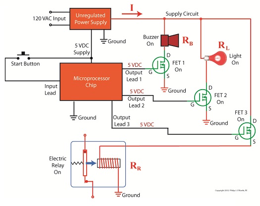
Transistors – Voltage Regulation Part VI
Sunday, August 26th, 2012

Transistors – Voltage Regulation Part V
Sunday, August 19th, 2012| I’m sure you’ve seen the television commercials warning about harmful interactions between prescription medications. By the same token electronic circuitry can also be adversely affected by certain combinations of electrical components, as we’ll discuss in today’s blog.
Last time we looked at a circuit schematic containing an unregulated power supply. This power supply was connected to an external supply circuit containing a number of components such as electric relays, buzzers, and lights. Each of these components has a resistance factor, and combined they have a total resistance of RTotal. We saw that when RTotal increases, the electrical current, I, decreases, and when RTotal decreases, I increases. In contrast to this increasing/decreasing activity of the total resistance RTotal, the fixed internal resistance of the unregulated power supply, RInternal, doesn’t fluctuate. Let’s explore Ohm’s Law further to see how the static effect of RInternal combines with the changing resistance present in RTotal to adversely affect the unregulated power supply output voltage, VOutput, causing it to fluctuate.
Figure 1
In Figure 1 RTotal and RInternal are operating in series, meaning they are connected together like sausage links. In this configuration their two resistances add together as if they were one larger resistor. Generally speaking, Ohm’s Law sets out that the current, I, flowing through a resistor in an electrical circuit equals the voltage, V, applied to the resistor divided by the resistance R, or: I = V ÷ R In the case of the circuit represented in Figure 1, the resistors RInternal and RTotal are connected in series within the circuit, so their resistances must be added together to arrive at a total power demand. Voltage is applied to these two resistors by the same voltage source, VDC. So, for the circuit as a whole Ohm’s Law would be written as: I = VDC ÷ (RInternal + RTotal) But, Ohm’s Law can also be applied to individual parts within the circuit, just as it can be applied to a single kitchen appliance being operated on a circuit shared with other appliances. Let’s see how this applies to our example circuit’s RTotal next week. ____________________________________________ |

Transistors – Voltage Regulation Part IV
Sunday, August 12th, 2012| We’ve all popped a circuit breaker sometime in our lives, often the result of making too heavy of an electrical demand in a single area of the house to which that circuit is dedicated. Like when you’re making dinner and operating the microwave, toaster, mixer, blender, food processor, and television simultaneously. The demand for current on a single circuit can be taxed to the max, causing it to pop the circuit breaker and requiring that trip to the electrical box to flip the switch back on.
Last time we began our discussion on unregulated power supplies and how they’re affected by power demands within their circuits. Our schematic shows there are two basic aspects to the circuit, namely, its direct current source, or VDC, and its internal resistance, RInternal. Now let’s connect the power supply output terminals to an external supply circuit through which electrical current will be provided to peripheral devices, much like all the kitchen gadgets mentioned above.
Figure 1
The external supply circuit shown in Figure 1 contains various electronic components, including electric relays, lights, and buzzers, and each of these has its own internal resistance. Combined, their total resistance is RTotal, as shown in our schematic. Current, notated as I, circulates through the power supply, through the external supply circuit, and then returns back to the power supply. The current circulates because the voltage, VDC, pushes it through the circuit like pressure from a pump causes water to flow through a pipe. RTotal and I can change, that is, increase or decrease, depending on how many components the microprocessor has turned on or off within the external supply circuit at any given time. When RTotal increases, electrical current, I, decreases. When RTotal decreases, electrical current I increases. Next time we’ll continue our discussion on Ohm’s Law, introduced last week, to show how the static effect of RInternal interacts with the changing resistance present in RTotal to adversely affect an unregulated power supply’s output voltage. ____________________________________________ |

Transistors – Voltage Regulation Part III
Tuesday, August 7th, 2012| When my daughter was seven she found out about Ohm’s Law the hard way, although she didn’t know it. She had accidentally bumped into her electric toy train, causing its metal wheels to derail and fall askew of the metal track. This created a short circuit, causing current to flow in an undesirable direction, that is, through the derailed wheels rather than along the track to the electric motor in the locomotive as it should.
What happened during the short circuit is that the bulk of the current began to follow through the path of least resistance, that of the derailed wheels, rather than the higher resistance of the electric motor. Electric current, always opportunistic, will flow along its easiest course, in this case the short, thick metal of the wheels, rather than work its way along the many feet of thin metal wire of the motor’s electromagnetic coils. With its wheels sparking at the site of derailment the train had become an electric toaster within seconds, and the carpet beneath the track began to burn. Needless to say, mom wasn’t very happy. In this instance Ohm’s Law was at work, with a decidedly negative outcome. The Law’s basic formula concerning the toy train would be written as: I = V ÷ Rwhere, I is the current flowing through the metal track, V is the track voltage, and R is the internal resistance of the metal track and locomotive motor, or in the case of a derailment, the metal track and the derailed wheel. So, according to the formula, for a given voltage V, when the R got really small due to the derailment, I got really big. But enough about toy trains. Let’s see how Ohm’s Law applies to an unregulated power supply circuit. We’ll start with a schematic of the power supply in isolation.
Figure 1The unregulated power supply shown in Figure 1 has two basic aspects to its operation, contained within a blue dashed line. The dashed line is for the sake of clarity when we connect the power supply up to an external circuit which powers peripheral devices later on. The first aspect of the power supply is a direct current (DC) voltage source, which we’ll call VDC. It’s represented by a series of parallel lines of alternating lengths, a common representation within electrical engineering. And like all electrical components, the power supply has an internal resistance, such as discussed previously. This resistance, notated RInternal, is the second aspect of the power supply, represented by another standard symbol, that of a zigzag line. Finally, the unregulated power supply has two output terminals. These will connect to an external supply circuit through which power will be provided to peripheral devices. Next time we’ll connect to this external circuit, which for our purposes will consist of an electric relay, buzzer, and light to see how it all works in accordance with Ohm’s Law. ____________________________________________ |


