| One way streets frustrate me, and I usually end up wasting a lot of time and gas driving in circles to get to my destination. Generally speaking, I prefer a two way street. Electric current flowing through electronic circuits is somewhat analogous to traffic flow. There are circuit paths that act like one way streets and others that act like two-way.
An electrical component called a diode can be used on circuit paths to govern the flow of current. They are a key component in basic transistorized voltage regulator circuits, as we’ll see later. For now, let’s get a basic understanding of how they work. Diodes are typically made of a semiconductor material, such as the element germanium. These materials behave in a complex way that fall along the lines of quantum physics. Esoteric phrases such as electron-hole theory, crystalline atomic lattice theory, and impurity doping are some of the concepts involved and would require a book onto themselves to explain. For the purposes of this article all we have to know is that semiconductors have two properties. The first property is that of an electrical conductor, that is, a material which allows electric current to pass through it. Copper wire is a good example of this. The second property is that of an electrical insulator, which blocks the flow of electric current. Materials such as glass, wood, and rubber fall into the insulator category. A photo of a diode is shown in Figure 1, along with its symbol used in electrical schematics.
Figure 1
When electric current flows through a diode in one direction, as shown in Figure 2, the semiconductor material inside of it acts as a conductor, ushering it along a single path.
Figure 2
When current tries to flow through the diode in the reverse direction, the semiconductor material acts as an insulator. That is, it blocks the flow of current as shown in Figure 3.
Figure 3
So we see that diodes can act like one way streets, restricting current flow. But, not all diodes work this way. Next week we’ll introduce a special kind of diode called the Zener diode, which allows current to flow in two different directions, and we’ll see how this functionality is put to work in regulated power supplies. ____________________________________________ |
Posts Tagged ‘electric circuit’
Transistors – Voltage Regulation Part IX
Sunday, September 16th, 2012


Transistors – Voltage Regulation Part V
Sunday, August 19th, 2012| I’m sure you’ve seen the television commercials warning about harmful interactions between prescription medications. By the same token electronic circuitry can also be adversely affected by certain combinations of electrical components, as we’ll discuss in today’s blog.
Last time we looked at a circuit schematic containing an unregulated power supply. This power supply was connected to an external supply circuit containing a number of components such as electric relays, buzzers, and lights. Each of these components has a resistance factor, and combined they have a total resistance of RTotal. We saw that when RTotal increases, the electrical current, I, decreases, and when RTotal decreases, I increases. In contrast to this increasing/decreasing activity of the total resistance RTotal, the fixed internal resistance of the unregulated power supply, RInternal, doesn’t fluctuate. Let’s explore Ohm’s Law further to see how the static effect of RInternal combines with the changing resistance present in RTotal to adversely affect the unregulated power supply output voltage, VOutput, causing it to fluctuate.
Figure 1
In Figure 1 RTotal and RInternal are operating in series, meaning they are connected together like sausage links. In this configuration their two resistances add together as if they were one larger resistor. Generally speaking, Ohm’s Law sets out that the current, I, flowing through a resistor in an electrical circuit equals the voltage, V, applied to the resistor divided by the resistance R, or: I = V ÷ R In the case of the circuit represented in Figure 1, the resistors RInternal and RTotal are connected in series within the circuit, so their resistances must be added together to arrive at a total power demand. Voltage is applied to these two resistors by the same voltage source, VDC. So, for the circuit as a whole Ohm’s Law would be written as: I = VDC ÷ (RInternal + RTotal) But, Ohm’s Law can also be applied to individual parts within the circuit, just as it can be applied to a single kitchen appliance being operated on a circuit shared with other appliances. Let’s see how this applies to our example circuit’s RTotal next week. ____________________________________________ |

Transistors – Digital Control Interface, Part V
Sunday, July 15th, 2012| Last time we looked at my electric relay solution to a problem presented by a 120 volt alternating current (VAC) drive motor operating within an x-ray film processing machine. Now let’s see what happens when we press the button to set the microprocessor into operation.
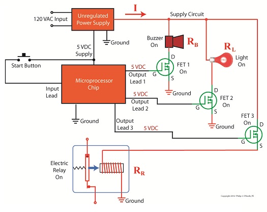
Figure 1Figure 1 shows that when the button is depressed, the computer program contained within the microprocessor chip goes into action, signaling the start of the control initiative. 5 volts direct current (VDC) is supplied to Output Lead 2, and FET 2 (Field Effect Transistor 2) becomes activated, which allows electric current from the 12 VDC supply to course into the 12 VDC electric relay, through the relay’s wire coil, then conclude its travel into electrical ground. The electric relay components, including a wire coil, steel armature, spring, and normally open (N.O.) contact, are shown within a blue box in our illustration. Current flow is represented by red lines. The control initiative passes from the microprocessor to FET 2, and then to the 12 VDC electric relay, just as the Olympic Torch is relayed through a system of runners. We learned in one of my previous articles on industrial control that when an electric relay coil is energized, electromagnetic attraction pulls its steel armature towards the wire coil and the N.O. electrical contact. In Figure 1 this attraction is represented by a blue arrow. With the N.O. contact closed the drive motor is connected to the 120 VAC input, and the motor is activated.
Figure 2
Figure 2 shows what happens after the button is depressed. The computer program is activated, directing the microprocessor chip to keep 5 VDC on Output Lead 2 and FET 2 while the prerequisite 40 minutes elapses. Thus the relay remains energized and the motor remains on during this time.
Figure 3
In Figure 3, at the end of the 40 minute countdown, the computer program applies 0 VDC to Output Lead 2. FET 2 then turns off the current flow to the relay and it begins to de-energize, causing the spring to pull the steel armature away from the N.O. contact and the 120 VAC power supply to be interrupted. The motor is deactivated. At the same time, the computer program applies 5 VDC to Output Lead 1 and FET 1 for 2 seconds. FET 1 turns on the flow of current through the buzzer, causing it to sound off and signal that the x-ray film processing machine is ready for use. Next time we’ll look at how transistors are used to regulate voltage within direct current power supplies like the one shown in Figure 3 above. ____________________________________________ |


Transistors
Sunday, June 10th, 2012| Back in the 60s my dad spent about $25 to buy a small transistor radio. That was a lot of money in those days, but well worth it. The new transistor technology allowed for a much less cumbersome radio to be produced. No more lugging around big radios armed with heavy vacuum tubes. In the years that followed the word transistor became a household word. They were employed in a variety of ways within televisions and other electronic devices, increasing both their reliability and functionality.
So what is a transistor and what does it do? It’s an electronic component, developed in the late 1940s. The first transistor was about as big as a softball and crudely made. As such, it was too impractical for commercial use. Then in the l950s technological advancements made commercial production of smaller, high-quality transistors possible. Transistors enjoyed widespread introduction to the consuming mainstream in the l960s, and since then they’ve been made in many different types, shapes, and sizes. Some are shown in Figure 1 below. Figure 1
A commonly used type of transistor is called a field effect transistor, or FET, one of which is shown in Figure 2. The FET has three metal leads which allow it to be connected into electrical circuits. These leads are referred to as the drain (D), the source (S), and the gate (G).
Figure 2
FET’s control the flow of current within an electronic circuit. A good way to understand what they do is to consider the analogy of water flowing through a faucet.
Figure 3
Figure 3 shows a faucet, complete with valve and handle. With the valve closed the flow of water is completely shut off. If the valve is opened partway by rotation of the handle, a trickle of water emerges. The more the handle is turned and valve is opened, the greater the flow of water. The FET shown in Figure 4 operates a lot like a faucet, but with regard to electrical current. Figure 4
The FET controls the flow of current flowing through its D and S leads, but it does not employ a valve or handle to do it. Rather, flow rate is controlled by application of a small amount of voltage to the G lead. The voltage’s influence on the G lead influences the FET to permit current to flow in through the D lead, then out through the S lead. The amount of voltage applied to the G lead is directly related to how much current will be allowed to flow. In this example the D lead on the FET is connected to a 10 volt direct current (VDC) power supply. The S lead is connected to a flashlight bulb which is connected to electrical ground. If you will remember from previous blogs, electric current naturally wants to flow from the supply source to ground, much like water wants to naturally flow downhill. If the bulb was connected directly to the 10 VDC power supply, current would flow through unimpeded and the bulb would light. However, in Figure 4 the FET acts as a regulating device. It’s connected between the 10 VDC power supply and the bulb. When no voltage is applied to the G lead the FET acts like a closed valve and current is unable to flow. Without current we, of course, have no light. When a low amount of voltage, say one volt, is applied to the G lead, the FET acts like a partially opened valve. It permits a trickle of current to flow from the 10 VDC supply to the bulb, and the bulb glows dimly. As voltage to G increases the FET valve opens further, permitting more current to flow. The bulb glows with increasing brightness. When the voltage applied to G increases to the point the FET valve is opened fully, in our example that is 2 volts, full current is allowed to flow from the 10 VDC supply to the bulb. The bulb glows brightly. Generally speaking, the voltage required to be applied to G for control of current flow through an FET depends on overall design and the particular application within an electrical circuit. FETs are often used within electronic devices to turn things on and off, with no other function in between. Next time we’ll look at some example circuits to see how it’s done. ____________________________________________ |


Industrial Control Basics – Electric Relay Example
Saturday, January 14th, 2012| When a starving monkey is faced with two buttons, one representing access to a banana, the other cocaine, which will he push? The cocaine, every time. The presence of buttons usually indicates a choice must be made, and electric relays illustrate this dynamic.
Last week we looked at a basic electric relay and saw how it was used to facilitate a choice in electricity flow between two paths in a circuit. Now let’s see what happens when we put a relay to use within a basic industrial control system making use of lit bulbs.
Figure 1
Figure 1 shows an electric relay that’s connected to both hot and neutral wires. At the left side is our pushbutton and the hot wire, on the right two bulbs, one lit, one not, and the neutral wire. No one is depressing the pushbutton, so an air gap exists, preventing current from flowing through the wire coil between the hot and neutral sides. With these conditions in place the relay is said to be in its “normal state.” The relaxed spring positioned on the relay armature keeps it touching the N.C. contact. This allows current to flow between hot and neutral through the armature and the N.C. contact. When these conditions exist the red bulb is lit, and this is accomplished without the need for anyone to throw a switch or press a button. In this condition the other lamp will remain disengaged and unlit. Now let’s refer to Figure 2 to see what happens when someone presses the button.
Figure 2
When the button is depressed the air gap is eliminated and the coil and wire become magnetized. They will attract the steel armature closer to them, the spring to expand, and the armature to engage with the N.O. contact. Under these conditions current will no longer flow along a path to light the red bulb because an air gap has been created between the armature and N.C. contact. The current instead flows through the N.O. contact, lighting the green bulb. It will stay lit so long as someone holds the button down. If our monkey were faced with the scenarios presented in Figures l and 2 and a banana was placed in the position of the red bulb, the cocaine in the position of the green, he might find that the regular delivery of bananas that takes place when the relay is in the N.C. contact position is enough to keep him happy. In this state he might be so full of bananas he won’t want to expend the energy to engage the button into the N.O. contact position for the delivery of cocaine. Next time we’ll revisit the subject of ladder diagrams and see how they are used to denote the paths of electric relays. ____________________________________________ |


Industrial Control Basics – Ladder Diagrams
Sunday, December 18th, 2011| The other day I pressed the button to activate my electric garage door opener and nothing happened. I pushed again and again, still nothing. Finally, I convinced myself to get out of the car and take a closer look. A wooden board I had propped up against the side of the garage wall had come loose, wedging itself in front of the electric eye, you know, the one that acts as a safety. The board was an obstruction to the clear vision of the eye. It couldn’t see the light emitter on the other side of the door opening and wouldn’t permit the door opener to function.
The basic manual control system we looked at last week operates similarly to the eye on a garage door opener. If you can’t “close the loop,” you won’t get the power. Last week’s example was as basic as things get. Now let’s look at something a bit more complex. Words aren’t always the best vehicle to facilitate understanding, which is why I often use visual aids in my work. In the field of industrial control systems diagrams are often used to illustrate things. Whether it’s by putting pencil to paper or the flow diagram of software logic, illustrations make things easier to interpret. Diagrams such as the one in Figure l are often referred to as “ladder diagrams,” and in a minute we’ll see why.
Figure 1 Figure 1(a) shows a basic manual control system. It consists of wires that connect a power switch and electric motor to a 120 volt alternating current power source. One wire is “hot,” the other “neutral.” The hot side is ungrounded, meaning that it isn’t electrically connected to the Earth. The neutral side is grounded, that’s right, it’s driven into the ground and its energy is dissipated right into the earth, then returned back to the power grid. In Figure 1(a) we see that the power switch is open and an air gap exists. When gaps exist, we don’t have a closed electrical loop, and electricity will not flow. Figure 1(b), our ladder diagram, aka line diagram, shows an easier, more simplified representation of the manual control shown in Figure 1(a). It’s easier to decipher because there’s less going on visually for the brain to interpret. Everything has been reduced to simple lines and symbols. For example, the electric motor is represented by a symbol consisting of a circle with an “M” in it. Now, let’s turn our attention to Figure 2 below to see what happens when the power switch is closed.
Figure 2 The power switch in Figure 2(a) is closed, allowing electric current to flow between hot and neutral wires, then power switch, and finally to the motor. The current flow makes the motor come to life and the motor shaft begins to turn. The line diagram for this circuit is shown in Figure 2(b). You might have noticed that the line diagrams show in Figures 1(b) and 2(b) have a rather peculiar shape. The vertically running lines at either side depict the hot and neutral legs of the system. If you stretch your imagination a bit, they look like the legs of a ladder. Between them run the wires, power switch, and motor, and this horizontal running line represents the rung of the ladder. More complicated line diagrams can have hundreds, or even thousands of rungs, making up one humongous ladder, hence they are commonly referred to as ladder diagrams. Next week we’ll take a look at two key elements in automatic control systems, the push button and electric relay, elements which allow us to do away with the need for human intervention. ____________________________________________ |


