Last time we looked at my electric relay solution to a problem presented by a 120 volt alternating current (VAC) drive motor operating within an x-ray film processing machine. Now let’s see what happens when we press the button to set the microprocessor into operation.
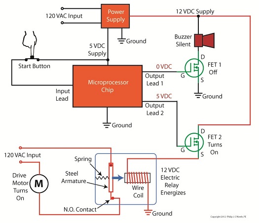
Figure 1Figure 1 shows that when the button is depressed, the computer program contained within the microprocessor chip goes into action, signaling the start of the control initiative. 5 volts direct current (VDC) is supplied to Output Lead 2, and FET 2 (Field Effect Transistor 2) becomes activated, which allows electric current from the 12 VDC supply to course into the 12 VDC electric relay, through the relay’s wire coil, then conclude its travel into electrical ground. The electric relay components, including a wire coil, steel armature, spring, and normally open (N.O.) contact, are shown within a blue box in our illustration. Current flow is represented by red lines. The control initiative passes from the microprocessor to FET 2, and then to the 12 VDC electric relay, just as the Olympic Torch is relayed through a system of runners. We learned in one of my previous articles on industrial control that when an electric relay coil is energized, electromagnetic attraction pulls its steel armature towards the wire coil and the N.O. electrical contact. In Figure 1 this attraction is represented by a blue arrow. With the N.O. contact closed the drive motor is connected to the 120 VAC input, and the motor is activated. Figure 2
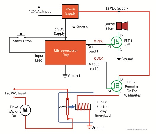
Figure 2 shows what happens after the button is depressed. The computer program is activated, directing the microprocessor chip to keep 5 VDC on Output Lead 2 and FET 2 while the prerequisite 40 minutes elapses. Thus the relay remains energized and the motor remains on during this time. Figure 3
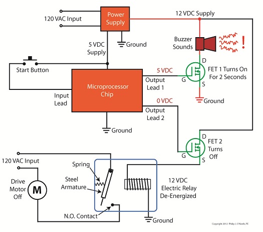
In Figure 3, at the end of the 40 minute countdown, the computer program applies 0 VDC to Output Lead 2. FET 2 then turns off the current flow to the relay and it begins to de-energize, causing the spring to pull the steel armature away from the N.O. contact and the 120 VAC power supply to be interrupted. The motor is deactivated. At the same time, the computer program applies 5 VDC to Output Lead 1 and FET 1 for 2 seconds. FET 1 turns on the flow of current through the buzzer, causing it to sound off and signal that the x-ray film processing machine is ready for use. Next time we’ll look at how transistors are used to regulate voltage within direct current power supplies like the one shown in Figure 3 above. ____________________________________________ |
Posts Tagged ‘normally open contact’
Transistors – Digital Control Interface, Part V
Sunday, July 15th, 2012Tags: armature, buzzer, computer program, design, electric circuit, electric drive motor, electric relay, electronic control, electronics, engineering expert witness, FET, field effect transistor, forensic engineer, industrial control, machine, microprocessor chip, microprocessor control, MOSFET, motor control, normally open contact, output lead, power supply, pushbutton, spring, transistor, voltage regulator, wire coil, x-ray film processing machine
Posted in Engineering and Science, Expert Witness, Forensic Engineering, Innovation and Intellectual Property, Personal Injury, Product Liability | Comments Off on Transistors – Digital Control Interface, Part V
Industrial Control Basics – Motor Overload Relay In Action
Sunday, March 18th, 2012|
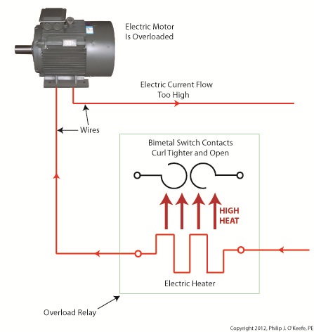
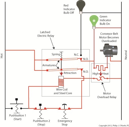
Last week we explored the topic of thermal expansion, and we learned how the bimetal contacts in a motor overload relay distort when heated. We also discussed how the overload relay comes into play to prevent overheating in electric motor circuits. Now let’s see what happens when an overload situation occurs. Figure 1
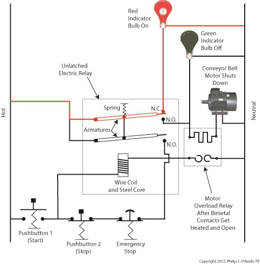
Figure 1 shows a motor becoming overloaded, as it draws in abnormally high amounts of electric current. Since this current also flows through the electric heater in the overload relay, the heater starts producing more heat than it would if the motor were running normally. This abnormally high heat is directed towards the bimetal switch contacts, causing them to curl up tightly until they no longer touch each other and open up. They will only close again when the overload condition is cleared up and the heater cools back down to normal operating temperature. Let’s now take a look at Figure 2 to see how the motor overload relay fits into our example of a conveyor belt motor control circuit. Once again, the path of electric current flow is denoted by red lines. Figure 2
The circuit in Figure 2 represents what happens after Button 1 is depressed. That is, the electric relay has become latched and current flows between hot and neutral sides through one of the N.O. contacts along the path of the green indicator bulb, the motor overload relay heater, and the conveyor belt motor. The current also flows through the other N.O. contact, the Emergency Stop button, Button 2, the electric relay’s wire coil, and the motor overload relay bimetal contacts. The motor becomes overloaded, causing the overload relay heater to produce abnormally high heat. This heat is directed towards the bimetal contacts, also causing them to heat up. Figure 3
In Figure 3 the bimetal contacts have heated to the point that they have curled away from each other until they no longer touch. With the bimetal contacts open, electric current is unable to flow through to the electric relay’s wire coil. This in turn ends the magnetic attraction which formerly held the relay armatures against the N.O. contacts. The spring in the electric relay has pulled the armatures up, causing the N.O. contacts to open, simultaneously closing the N.C. contact. These actions have resulted in a loss of current to the green indicator bulb and electric motor. The red indicator bulb is now activated, and the conveyor motor is caused to automatically shut down to prevent damage and possible fire due to overheating. This means that even if the conveyor operator were to immediately press Button 1 in an attempt to restart the line, he would be prevented from doing so. Under these conditions the electric relay is prevented from latching, and the motor remains shut down because the bimetal contacts have been separated, preventing current from flowing through to the wire coil. The bimetal contacts will remain open until they once again cool to normal operating temperature. Once cooled, they will once again close, and the motor can be restarted. If the cause of the motor overload is not diagnosed and its ability to recur eliminated, the automatic shutdown process will repeat this cycle. Next time we’ll see how the overload relay is represented in a ladder diagram. We’ll also see how switches can be added to the circuit to allow maintenance staff to safely work. ____________________________________________
|
Tags: automatic control, bimetalic contacts, closed contact, controls engineer, electric current, electric relay, emergency stop, engineering expert witness, fire, forensic engineer, heater, hot, indicator bulb, industrial control, motor control, motor damage, motor overload, motor overload relay, N.C. contact, N.O. contact, neutral, normally closed contact, normally open contact, open contact, pushbutton
Posted in Engineering and Science, Expert Witness, Forensic Engineering, Innovation and Intellectual Property, Personal Injury, Product Liability, Professional Malpractice | Comments Off on Industrial Control Basics – Motor Overload Relay In Action
Industrial Control Basics – Unlatching the Latching Circuit
Sunday, February 5th, 2012| When I had the misfortune of getting stuck in my Uncle Jake’s outhouse as a kid, I would allow my hysteria to get the best of me and forget my uncle’s instructions on how to get out. It was a series of raps and a single kick that would prove to be the magic formula, and once I had calmed myself down enough to employ them I would succeed in working the door’s rusty latch open. Our relay circuit below has a much less challenging system to effectively unlatch the pattern of electric current.
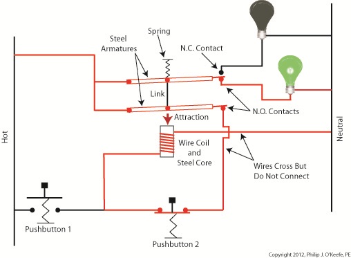
Figure 1 shows our latched circuit, where red lines denote the flow of current. Figure 1
If you recall, the relay in this circuit was latched by pressing Pushbutton 1. When in the latched state, the magnetic attraction maintained by the wire coil and steel core won’t allow the relay armatures to release from their N.O. contacts. The relay’s wire coil stays energized via Button 2, the red bulb goes dark while the green bulb remains lit, even though Button 1 is no longer actively depressed. Now let’s take a look at Figure 2 to see how to get the circuit back to its unlatched state. Figure 2
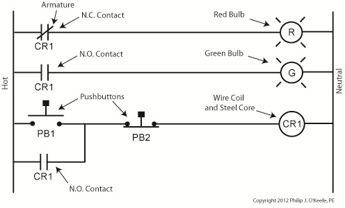
With Button 2 depressed the flow of current is interrupted and the relay’s wire coil becomes de-energized. In this state the coil and steel core are no longer magnetized, causing them to release their grip on the steel armatures. The spring will now pull them back until one of them makes contact with the N.C. contact. The red bulb lights again, although Button 2 is not being actively depressed. At this point the electric relay has become unlatched. It can be re-latched by depressing Button 1 again. Let’s see how we can simplify Figure 2’s representation with a ladder diagram, as shown in Figure 3. Figure 3
We’ve seen how this latching circuit activates and deactivates bulbs. Next time we’ll see how it controls an electric motor and conveyor belt inside a factory. ____________________________________________ |
Tags: armature, bulbs, button, electric relay, electrical engineering, engineering expert witness, forensic engineer, hot neutral, industrial control, ladder diagram, latched relay, magnetism, mechanical relay, N.C. contact, N.O. contact, normally closed contact, normally open contact, pushbutton, pushbutton control, relay ladder logic, spring, unlatching a relay, wire, wire coil
Posted in Engineering and Science, Expert Witness, Forensic Engineering, Innovation and Intellectual Property, Personal Injury, Product Liability, Professional Malpractice | Comments Off on Industrial Control Basics – Unlatching the Latching Circuit
Industrial Control Basics – Electric Relay Example
Saturday, January 14th, 2012| When a starving monkey is faced with two buttons, one representing access to a banana, the other cocaine, which will he push? The cocaine, every time. The presence of buttons usually indicates a choice must be made, and electric relays illustrate this dynamic.
Last week we looked at a basic electric relay and saw how it was used to facilitate a choice in electricity flow between two paths in a circuit. Now let’s see what happens when we put a relay to use within a basic industrial control system making use of lit bulbs. Figure 1
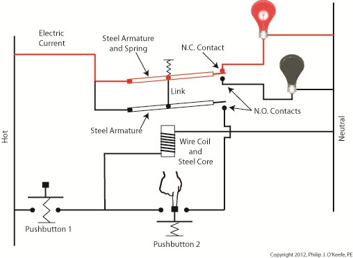
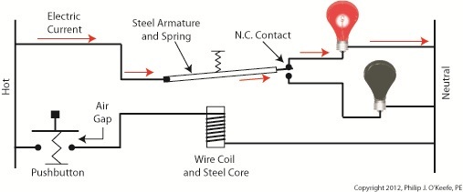
Figure 1 shows an electric relay that’s connected to both hot and neutral wires. At the left side is our pushbutton and the hot wire, on the right two bulbs, one lit, one not, and the neutral wire. No one is depressing the pushbutton, so an air gap exists, preventing current from flowing through the wire coil between the hot and neutral sides. With these conditions in place the relay is said to be in its “normal state.” The relaxed spring positioned on the relay armature keeps it touching the N.C. contact. This allows current to flow between hot and neutral through the armature and the N.C. contact. When these conditions exist the red bulb is lit, and this is accomplished without the need for anyone to throw a switch or press a button. In this condition the other lamp will remain disengaged and unlit. Now let’s refer to Figure 2 to see what happens when someone presses the button. Figure 2
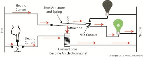
When the button is depressed the air gap is eliminated and the coil and wire become magnetized. They will attract the steel armature closer to them, the spring to expand, and the armature to engage with the N.O. contact. Under these conditions current will no longer flow along a path to light the red bulb because an air gap has been created between the armature and N.C. contact. The current instead flows through the N.O. contact, lighting the green bulb. It will stay lit so long as someone holds the button down. If our monkey were faced with the scenarios presented in Figures l and 2 and a banana was placed in the position of the red bulb, the cocaine in the position of the green, he might find that the regular delivery of bananas that takes place when the relay is in the N.C. contact position is enough to keep him happy. In this state he might be so full of bananas he won’t want to expend the energy to engage the button into the N.O. contact position for the delivery of cocaine. Next time we’ll revisit the subject of ladder diagrams and see how they are used to denote the paths of electric relays. ____________________________________________ |
Tags: armature, bulb, coil, electric circuit, electric current, electric relay example, electricity flow, electro-mechanical relay, electromagnet, engineering expert witness, forensic engineer, hot, hot wire, industrial control, lamp, N.C. contact, N.O. contact, NC contact, neutral, neutral wire, NO contact, normal state, normally closed contact, normally open contact, pushbutton, relay, spring, switch, wire coil
Posted in Engineering and Science, Expert Witness, Forensic Engineering, Innovation and Intellectual Property, Personal Injury, Product Liability, Professional Malpractice | 1 Comment »
