|
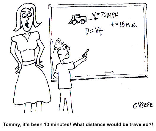
Last week we talked about one of the ten core disciplines of mechanical engineering, statics. Today our focus will shift to a discussion of how mechanical engineers use the study of Dynamics to solve problems. As its name implies, Dynamics involves the study of how things change, or more specifically, how they move. Dynamics can be broken down into two basic parts: kinematics and kinetics. We’ll focus on kinematics this week. Kinematics is the study of the geometry of motion. Kinematics is used to develop a relationship between how far an object travels in a given time, its velocity, and its acceleration. The precipitating cause of the motion is not considered in kinematics. Before beginning our discussion of kinematics, let’s go back to the good ol’ days and revisit what should be some very familiar ground to anyone who’s taken algebra. Does this word problem sound familiar to you: If you start at point X and you’re going at Y speed for a given length of time, T, what distance will you have traveled? Here’s the same problem presented in another way. Suppose you’re driving and you set your cruise control at 70 miles per hour. Out of curiosity you want to know how far your automobile will travel in 15 minutes (0.25 hours). Kinematics teaches that the relationship between velocity, time, and distance can be demonstrated by this equation: Distance = (Velocity) x (Travel Time) Distance = (70 miles/hour) x (0.25 hour) = 17.5 miles Of course kinematics can get far more complicated than this simple example, especially when objects accelerate, decelerate, change direction, and move in paths that are nonlinear, that is, not in a straight line. Next week we’ll talk about the study of kinetics, particularly Sir Isaac Newton’s Second Law of Motion. _________________________________________________________________ |
Archive for October, 2009
Mechanical Engineering, Focus on Dynamics – Part I, Kinematics
Sunday, October 25th, 2009Utility Patent Basics
Wednesday, October 21st, 2009|
During my engineering career, I’ve encountered quite a few business owners and inventors who are completely in the dark when it comes to intellectual property rights. In particular, there are plenty of misconceptions floating around about utility patents. To learn more about utility patents, I invite you to read an excellent article by attorney Thomas F. Zuber: Patent Law Basics For The Non-practitioner – Part II Of IV: UTILITY PATENTS *This article is for non-practitioners seeking to familiarize themselves with the basics of patent types and patentability requirements. This article is Part II of a four part series. Parts III and IV will follow in biweekly installments, and will address Design Patents and Plant Patents, respectively. Utility patents are the most common type of patent, and they’re what laypersons are usually referring to when using the word “patent.” For an invention to be patented, ….. Read the full article by going to: ________________________________________________________________ |
Mechanical Engineering, Focus on Statics
Sunday, October 18th, 2009|
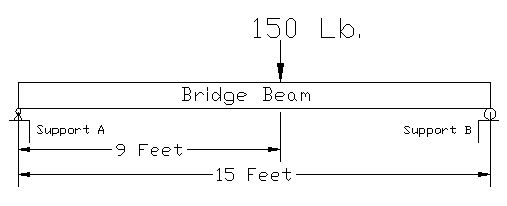
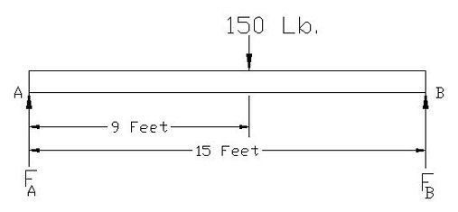
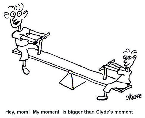
As I stated in my last blog post, Statics is the study of how forces are transmitted to and throughout stationary objects. Let’s learn a little bit about how statics is used by mechanical engineers to solve problems. Consider a perfectly rigid bridge beam sitting on two supports (see Figure 1). Now suppose you decide to stand on it. The weight of your body would push down on the beam, creating a system of forces that act upon the beam. If the beam stays on its supports and doesn’t move (it remains static), then the forces are said to be in “equilibrium.” In other words, since the beam doesn’t move when you stand on it, the sum of all the forces acting upon it are zero. Figure 1 So what, you say? Well, this concept of forces in equilibrium helps mechanical engineers analyze external and internal forces acting on stationary objects that have importance to us in real life, like bridges, machines, traffic signal masts, etc. This analysis is used to calculate the magnitudes of all the forces acting on these objects so they can design parts of the objects to be strong enough not to break apart. Think about that next time you get ready to cross a bridge in your car. To show how this works, consider the bridge beam scenario I discussed above. Suppose you weigh 150 pounds and you stand nine feet from the left end of the bridge beam (see Figure 2). Your weight will exert a downward force of 150 pounds upon the beam (let’s ignore the weight of the beam in this case). The weight of your body creates reaction forces on the beam at Support A and Support B. To consider these reaction forces, the mechanical engineer would draw what is called a “free body diagram” (see Figure 3). Figure 2 Figure 3 The reaction forces (FA and FB) at the supports A and B push up on the bottom of the beam. If the beam remains static, then the sum of the reaction forces will equal the 150 pound weight force from your body. That is, the reaction forces cancel out the 150 pound force if the beam doesn’t move and they are said to be in equilibrium. But in our example above, you’re not standing in the exact center of the beam, hence the two reaction forces are not going to be equal. More of your body weight force is bearing down on Support B and less on Support A. So how do you determine the values of the reaction forces in a situation like this? You consider “moments.” A moment is mechanical engineering lingo for a force multiplied by a distance. Moments want to rotate objects. This is an important concept in statics because if an object doesn’t move, it certainly won’t rotate, so the sum of all the moments acting on the object are zero. So, in the case of our bridge beam, the sum of the moments acting on Support A would be zero, or mathematically speaking: Sum MA = [(FA) x (0 Feet)] – [(150 Lb.) x (9 Feet)] + [(FB) x (15 Feet)] = 0 Using algebra, you can find the value for the reaction force at Support B: [0] – [(150 Lb.) x (9 Feet)] + [(FB) x (15 Feet)] = 0 [(FB) x (15 Feet)] = [(150 Lb.) x (9 Feet)] FB = 90 Lb. So what about the reaction force at Support A? If you remember, I said that if the bridge beam remains static, then the sum of all the forces acting on it will be zero. Knowing that, you can use algebra to solve for the reaction force at Support A: FA -150 Lb + FB = 0
FA = 150 Lb. – 90 Lb. = 60 Lb. So that is the basic concept of statics. Remember, in statics, nothing moves, so mechanical engineers use that to their advantage when they analyze forces acting on objects. Our next topic will be: Dynamics, the study of the effects of velocity and acceleration and resulting forces and the energy of moving objects. Last week’s Riddle: Everyone knows us to be racing by when they look at a clock, but mechanical engineers also know us to add up to zero when they look at a fixed structure. What are we? Answer: Moments _________________________________________________________________ |
Mechanical Engineering, Not Just About Gears
Sunday, October 11th, 2009|
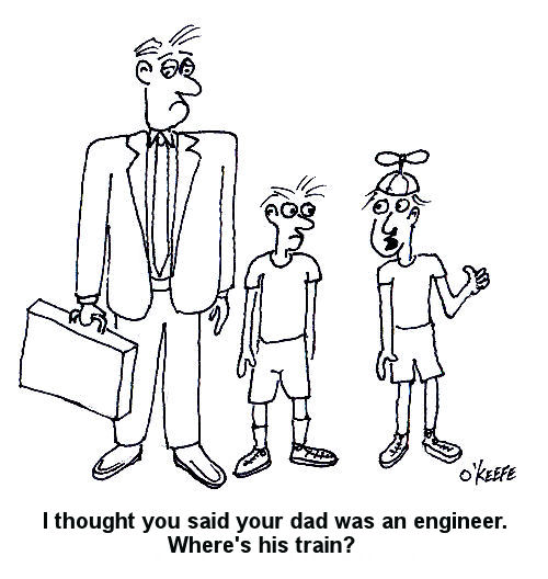
When I was a kid I had a friend who thought that everyone who said they were an engineer wore pinstriped bib overalls and drove trains. Funny thing is, I later became both a locomotive engineer and a degreed mechanical engineer, but that’s a story for another time. Speaking of engineers, what do you think of when you hear the words, “mechanical engineer?” If you’re like most, you probably think of someone who designs gears and machinery. But the field of mechanical engineering is far more complex than that. Mechanical engineering is one of the oldest and broadest of engineering disciplines. It encompasses a broad number of disciplines, from physics to materials science, but it can be summarized as being derived from ten core areas:
Armed with this knowledge, mechanical engineers can take on design projects ranging from airplane propellers to utility power plants. During the coming weeks we will focus on each of these areas and explore them more fully. We may even have a little quiz at the end to test your newfound knowledge! Our first topic will be: Statics, the study of how forces are transmitted to and throughout stationary objects. And here is a riddle to get you started in your personal exploration of the subject matter: Everyone knows us when they look at a clock, but mechanical engineers also know us to add up to zero when they look at a fixed structure. What are we? Get the answer in my next blog post. _________________________________________________________________ |
Forensic Engineering Focus On Electrical Fires
Sunday, October 4th, 2009|
Property damage and loss of lives, these are often the result of fires. But did you know that one of the leading causes of fire is electricity? Residential electrical fires claim the lives of nearly 500 Americans each year and injure another 2300. Annually, these fires result in over $800 million in property losses. Approximately one third of the nearly 70,000 home electrical fires that occur each year are traceable to design and manufacturing defects in electrical products. The rest are caused by the misuse and poor maintenance of electrical products, overloaded circuits and extension cords, and incorrectly installed wiring. The three components that must be present in order for a fire to manifest and sustain itself are well known. These components make up the “Fire Triangle,” a potentially lethal combination of heat, fuel, and oxygen. If any one of these three components is missing from the triangle, a fire can’t be started or sustained. In the case of an electrical fire, it’s electricity that creates the heat component of the Fire Triangle.
The Fire Triangle How does electricity contribute to fires? One example would be an overloaded extension cord. Homeowners are sometimes unaware that extension cords must be sized appropriately for their ultimate usage. If not, they can overheat, particularly if they are damaged. Damage to cords can result from a myriad of factors, from factory production errors to kinking when heavy furniture is carelessly placed on top of them. The same principle holds true for electrical products. If their internal wiring or a component is insufficiently sized or damaged, overheating can result. If things get hot enough and there is sufficient airflow (oxygen) and combustible material (fuel) in the vicinity, then the fire triangle is complete. The fire starts internally and can soon spread to other objects in the area. Electrical arcing can occur when an energized electrical circuit is broken. For example, suppose a wire carrying current is suddenly broken in two. If the voltage is high enough, the electricity will want to continue to flow through the air across the break to form an electrical arc. If the power flowing through the arc is great enough, heat can once again complete the Fire Triangle, resulting in fire. Forensic engineering analysis of evidence collected from a fire scene often yields telltale signs of overheating due to overloaded electrical circuits or damaged wiring in components. Under close examination by an experienced professional, even the smallest strand of wire can point to the cause of an electrical fire. CSI skills aren’t only employed at crime scenes. Forensic engineers also use similar techniques to get to the true story of cause and effect. _________________________________________________________________ |
