Posts Tagged ‘kinetics’
Vibration Analysis in Mechanical Engineering, Part II
Sunday, March 14th, 2010Vibration Analysis in Mechanical Engineering, Part I
Sunday, March 7th, 2010|
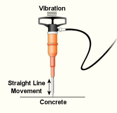
Last week we wrapped up our discussion on heat transfer. This week we’ll turn to a discussion on vibration analysis. Vibration occurs when there is physical movement of a machine part when compared to a point of reference. This physical movement can manifest in a straight line, a circle, or any way imaginable in three dimensions. The point of reference can be a guideway for a sliding part or a shaft for a rotating part. As discussed in kinetics, machine parts have mass, and when mass moves it contains kinetic energy, so it makes sense that when a part moves within a machine, the energy created can result in forces that act upon the machine as a whole. The net result is machine vibration which occurs in “sympathy” with the movement of the original mechanical part under discussion. Let’s talk about examples of vibration caused by straight line and circular motion. And what figure conjures up a better image of up-and-down straight line vibration then a jackhammer, as shown in Figure 1. This tool has a chisel which is attached to an air piston that moves up and down in a straight line, and the chisel and piston each have mass. It is the rapid up and down movement of the total mass of the device that results in concrete-breaking force. Unfortunately, those forces also vibrate back up the jackhammers shaft into the hands, arms and body of the construction worker operating it. Figure 1 – A Jackhammer
An example of vibration caused by circular movement can be found in your washing machine. Ever notice what happens when you throw one heavy object, say a throw rug, into it, and it begins the spin cycle? That “THUMP-THUMP-THUMP” sound that just won’t quit is due to the rug, now wet and congealed into a single heavy lump to one side of the agitator. It continues to spin about the center of the agitator, creating an unbalanced outward centrifugal force that keeps changing direction around its central pivot point, the agitator. This force makes the washing machine want to rock from side to side and front to back. Now imagine this situation taking place inside your washer day after day, hour after hour, every time you put a load to wash. How long do you think your washer would last under this usage? As this example illustrates, vibrations must be considered in machine design because if they are severe enough, they can cause machine parts to prematurely wear and fail. Speaking of wear and failure, you might have discovered how the tires on your car wore out prematurely and a mechanic said this happened because your shock absorbers or struts are bad. Shock absorbers and struts help to safely control, or “dampen,” vibrations in the suspension system that result when your car’s wheels roll down the highway. Without proper damping, the vibration forces can cause your tire to literally bounce down the road and grind on the pavement with each landing. Oh, yes, if the vibration is strong enough, you can even lose control of your car and end up in a crash. Unfortunately, strong vibrations do not only affect machinery, but the people that come into contact with them, often causing physical discomfort and injury. Ever heard of “white finger syndrome,” otherwise known as Raynaud’s syndrome? This painful condition, which results when vibrations impair blood flow to the fingers, causes them to tingle, feel numb, and then turn white. The longer a person uses a vibrating tool, and the faster the tool vibrates, the greater the risk. Well that’s our initial plunge into the world of vibrations. Now that we know the basics of what vibrations are and what they can do, next time we can explore how to resolve a straightforward vibration problem which often presents itself in rotating mechanisms. _________________________________________________________________ |
Mechanical Engineering, Focus on Dynamics, Part II, Kinetics
Monday, November 2nd, 2009|
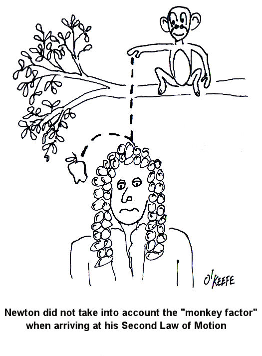
In Part I of Mechanical Engineering, Focus On Dynamics, we talked about kinematics. This week in Part II, we’ll talk about kinetics. Kinetics is the study of the relationship that exists between forces acting on a body, the mass of the body itself, and its motion. It’s used to predict the motion caused by given forces acting on a body or to determine the forces required to produce a motion of the body. In kinetics forces can be attributed to the motion of an object by way of Sir Isaac Newton’s Second Law of Motion. In other words, this law relates the kinematics of an object to the forces applied to it, and in equation form that relationship looks like this: Force = [Mass] x [Acceleration] “Mass” is the weight of the object, in pounds, divided by the acceleration of the Earth’s gravity. On Earth, the acceleration of gravity is considered to be a constant and is taken to be 32.2 feet per second, per second. (No, that’s not a typo.) Legend has it that Newton discovered the earth’s acceleration when gravity caused an apple to fall from a tree and hit him on the head. That may or may not be true, but Newton’s Second Law of Motion forms the foundation for the study of kinetics. To illustrate how kinetics works, we can look at another very simple example. Suppose you have a block of steel that weighs 50 pounds, and it is sitting still on a nice smooth, frictionless sheet of ice (see Figure 1). Figure 1
How hard would you have to push on the side of this block to make it accelerate across the ice at a rate of 10 feet per second, per second? Use Newton’s second law to find out: Force = [(50 Lb.) ÷ (32.2 ft./second2)] x [10 ft./second2] Force = 15.5 Lb. Force and energy calculations in kinetics can get really complicated, especially when you have to consider the effects of friction, forces acting at angles, velocity, rotation, motion constraints, collisions, etc. Our next mechanical engineering topic will be: Kinematics of Machines, the study of how parts of machines behave as they move through their ranges of motion. _________________________________________________________________ |
Mechanical Engineering, Focus on Dynamics – Part I, Kinematics
Sunday, October 25th, 2009|
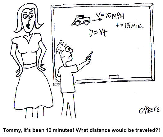
Last week we talked about one of the ten core disciplines of mechanical engineering, statics. Today our focus will shift to a discussion of how mechanical engineers use the study of Dynamics to solve problems. As its name implies, Dynamics involves the study of how things change, or more specifically, how they move. Dynamics can be broken down into two basic parts: kinematics and kinetics. We’ll focus on kinematics this week. Kinematics is the study of the geometry of motion. Kinematics is used to develop a relationship between how far an object travels in a given time, its velocity, and its acceleration. The precipitating cause of the motion is not considered in kinematics. Before beginning our discussion of kinematics, let’s go back to the good ol’ days and revisit what should be some very familiar ground to anyone who’s taken algebra. Does this word problem sound familiar to you: If you start at point X and you’re going at Y speed for a given length of time, T, what distance will you have traveled? Here’s the same problem presented in another way. Suppose you’re driving and you set your cruise control at 70 miles per hour. Out of curiosity you want to know how far your automobile will travel in 15 minutes (0.25 hours). Kinematics teaches that the relationship between velocity, time, and distance can be demonstrated by this equation: Distance = (Velocity) x (Travel Time) Distance = (70 miles/hour) x (0.25 hour) = 17.5 miles Of course kinematics can get far more complicated than this simple example, especially when objects accelerate, decelerate, change direction, and move in paths that are nonlinear, that is, not in a straight line. Next week we’ll talk about the study of kinetics, particularly Sir Isaac Newton’s Second Law of Motion. _________________________________________________________________ |
