|
Could it be that after cave men invented the wheel they moved on to invent another circular object, the gear? Gear assemblies are found in a wide variety of applications, from tiny ones used inside wrist watches to massive ones found in aircraft carriers. No one knows for certain when gear technology was first employed, but we do know that gear driven machinery has been around since before the Industrial Revolution. As far back as the Renaissance we’ve documented their use within flour milling equipment and the first primitive clocks. Going even further back in time, Roman engineers are known to have developed a primitive gear driven odometer. It was attached to horse drawn cart wheels and the number of revolutions performed allowed the distance traveled to be calculated. In fact gears have been used far longer than scientists originally thought. In October of the year 1900 sponge divers stumbled upon an ancient Roman shipwreck at the bottom of the Aegean Sea near the Greek island of Antikythera. Inside this wreck they found mineral encrusted fragments of an artifact composed of a bronze alloy. This amazing discovery appeared to be a remarkably modern looking gear assembly which would come to be known as the Antikythera Mechanism.
Analysis of the Mechanism conducted over the last 100 years has revealed it to be a highly complex device. Still visible engraved inscriptions disclose it to be of Greek origin, dating back to about 100 BC. As such it’s the oldest known complex gear driven mechanism in the world. Prior to its discovery it was thought that mechanisms of its kind were not made until 1400 AD. As to the purpose it served, that remains a subject of controversy, since many of its parts are missing.
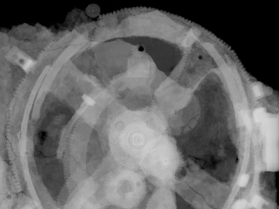
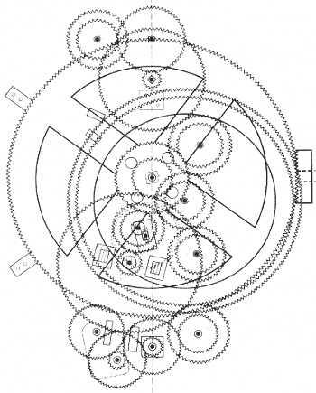
The X-ray image reveals some of the Mechanism’s hidden complexity. Based on detailed examination of these images coupled with engineering analysis, it’s theorized by scientists that the mechanism may have been configured as illustrated below.
Since there’s no evidence that ancient Greeks possessed motors, such as those used in modern clocks, some scientists believe that the gears in the Mechanism were set into motion by simply turning a hand crank. Others believe that the arrangement and size of the gears indicate that the Mechanism’s movement is analogous to planetary motion within our solar system. They theorize further that it may have been used to calculate the positions of the Sun, Moon, and other celestial bodies. Next time we’ll fast forward to present day to familiarize ourselves with the basic terminology of gears and then later see how they’re used in modern devices.
________________________________________ |
Archive for December, 2013
The History of Gears
Monday, December 23rd, 2013See How a Centrifugal Clutch Works With Animation
Monday, December 16th, 2013|
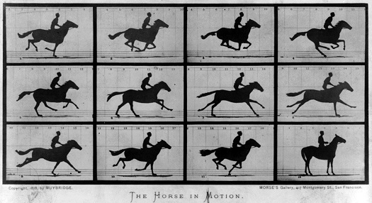
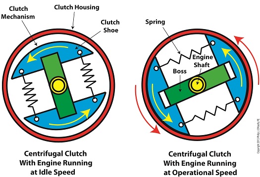
Ever wondered if a running horse lifts all four of its feet off the ground at the same time? Leland Stanford, an industrialist and horseman of the late 19th Century did, and he hired photographer Eadweard Muybridge to find out. Muybridge’s series of 24 photographs of Stanford’s horse, Sallie Gardner, came to be known as Sallie Gardner at a Gallop and is regarded to be an early example of silent film. The Muybridge photos were viewed at increased speed on a zoopraxiscope, a device he invented in 1879. A precursor to modern movie projectors, it projected a series of independent photographs as a moving image through the use of multiple cameras shooting the subject at different points in time. In this way it was disclosed that yes, indeed, there were moments when all four of a galloping horse’s feet hover in mid air. Today’s moving images are displayed at between 24 and 300 fps, depending on the application. Muybridge’s experiment proved that not only are moving images more engaging than static ones, they are also more explicit, able to convey information still images are not. Take for example this series of stills of a centrifugal clutch assembly. Are you able to tell by looking at these two-dimensional images how a clutch works? How as the engine speeds up the spinning shoes move out and make contact with the clutch housing, this pressure causing the entire assembly to spin? Unless you’re familiar with clutches, probably not. Now here’s the same clutch brought to life through animation:
In today’s fast paced, internet-laden society, people’s attention spans are shorter than ever, and their demands to be visually engaged are high. It’s been proven that holding a modern day viewer’s attention for more than three seconds is a difficult task. This truth is evident in the courtroom as well, where trial attorneys are obliged to increase the production value of evidence presented in order to win over juries, and animation is becoming their tool of choice. What held true more than 100 years ago still holds true today: Nothing tells a story like a moving image. Next time we’ll switch gears, quite literally, to understand how a series of gears work together to power machinery. ________________________________________ Note: If you are viewing this blog article in an email and the animation video does not appear, then click on this link to view the article with your web browser. ________________________________________ |
How Condensers Increase Efficiency Inside Power Plants
Wednesday, December 4th, 2013|
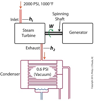
Last time we ran our basic power plant steam turbine without a condenser. In that configuration the steam from the turbine exhaust was simply discharged to the surrounding atmosphere. Today we’ll connect it to a condenser to see how it improves the turbine’s efficiency. As discussed in a previous blog, enthalpy h1 is solely dependent on the pressure and temperature at the turbine inlet. For purposes of today’s discussion, turbine inlet steam pressure and temperature will remain as last time, with values of 2,000 lbs PSI and 1000°F respectively, and calculations today will be based upon those values. So to review, the inlet enthalpy h1 is, h1 = 1474 BTU/lb If the condenser vacuum exists at a pressure of 0.6 PSI, a realistic value for a power plant condenser, then referring to the steam tables in the Van Wylen and Sonntag thermodynamics book, we find that the enthalpy h2 will be, h2 = 847 BTU/lb and the amount of useful work that the turbine can perform with the condenser in place would therefore be, W = h1 – h2 = 1474 BTU/lb – 847 BTU/lb = 627 BTU/lb So essentially with the condenser present, the work of the turbine is increased by 168 BTU/lb (627 BTU/lb – 459 BTU/lb). To put this increase into terms we can relate to, consider this. Suppose there’s one million pounds of steam flowing through the turbine each hour. Knowing this, the turbine power increase, P, is calculated to be, P = (168 BTU/lb) ´ (1,000,000 lb/hr) = 168,000,000 BTU/hr Now according to Marks’ Standard Handbook for Mechanical Engineers, a popular general reference book in mechanical engineering circles, one BTU per hour is equivalent to 0.000393 horsepower, or HP. So converting turbine power, P, to horsepower, HP, we get, P = (168,000,000 BTU/hr) ´ (0.000393 HP/BTU/hr) = 66,025 HP A typical automobile has a 120 HP engine, so this equation tells us that the turbine horsepower output was increased a great deal simply by adding a condenser to the turbine exhaust. In fact, it was increased to the tune of the power behind approximately 550 cars! What all this means is that the stronger the vacuum within the condenser, the greater the difference between h1 and h2 will be. This results in increased turbine efficiency and work output, as evidenced by the greater numeric value for W. Put another way, the turbine’s increased efficiency is a direct result of the condenser’s vacuum forming action and its recapturing of the steam that would otherwise escape from the turbine’s exhaust into the atmosphere. This wraps up our series on the power plant water-to-steam cycle. Next time we’ll use the power of 3D animation to turn a static 2D image of a centrifugal clutch into a moving portrayal to see how it works. ________________________________________ |

