|
In this blog series we’ve been examining gear train usefulness, specifically in terms of increasing torque. Equations presented last week began us on the final leg of our journey, and we’ve arrived at the point where the closing combination of equations will demonstrate the loss of speed that takes place when torque is increased within a gear train. To that end, the two main equations under consideration as presented last week, are:
where R is the gear ratio of the gear train, N is the number of gear teeth, n is the gear rotational speed in revolutions per minute (RPM), T is the torque, and D is the gear pitch radius. We were able to link these two equations by working through five key design equations applicable to simplified gear trains. For the full step-by-step progression see last week’s blog. After working through the equations presented last time we were able to arrive at an equation which links equations (1) and (2). Here it is:
If you follow the color coding, you’ll see the elements of equations (1) and (2) which come together in equation (7). Because equation (7) links the gear speed ratios (red) with the gear pitch radii ratios (green), we can set the ratios in equation (1) equal to those in equation (2). Doing so, we get: R = NDriven ÷ NDriving = nDriving ÷ nDriven = DDriven ÷ DDrivng = TDriven ÷ TDriving
In order to see the tradeoff between speed and torque, we need only consider the parts of the equation which concern themselves with factors relating to speed and torque. Removing the other unnecessary factors, we arrive at:
Next week we’ll plug numbers into equation (8) and disclose the tradeoff of speed for torque.
_______________________________________
|
Posts Tagged ‘gear design’
Determining the Gear Train Tradeoff of Torque vs. Speed, Part Two
Wednesday, August 20th, 2014Gear Reduction
Wednesday, March 5th, 2014|
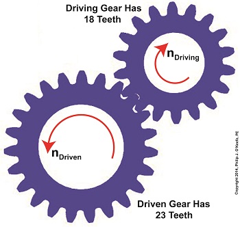
Last time we learned there are two formulas used to calculate gear ratio, R. Today we’ll see how to use them to calculate a gear reduction between gears in a gear train, a strategy which enables us to reduce the speed of the driven gear in relation to the driving gear. If you’ll recall from last time, our formulas to determine gear ratio are: R = NDriven ÷ NDriving (1) R = nDriving ÷ nDriven (2) Now let’s apply them to this example gear train to see how a gear reduction works. Here we have a driven gear with 23 teeth, while the driving gear has 18. For our example the electric motor connected to the driving gear causes it to turn at a speed, nDriving, of 3600 revolutions per minute (RPM). Knowing these numerical values we are able to determine the driven gear speed, nDriven. First we’ll use Formula (1) to calculate the gear ratio using the number of teeth each gear has relative to the other: R = NDriven ÷ NDriving R = 23 Teeth ÷ 18 Teeth R = 1.27 In gear design nomenclature, the gear train is said to have a 1.27 to 1 ratio, commonly denoted as 1.27:1. This means that for every tooth on the driving gear, there are 1.27 teeth on the driven gear. Interestingly, the R’s in both equations (1) and (2) are identical, and in our situation is equal to 1.27, although it is arrived at by different means. In Formula (1) R is derived from calculations involving the number of teeth present on each gear, while Formula (2)’s R is derived by knowing the rotational speeds of the gears. Since R is the common link between the two formulas, we can use this commonality to create a link between them and insert the R value determined in one formula into the other. Since we have already determined that the R value is 1.27 using Formula (1), we can replace the R in Formula (2) with this numerical value. As an equation this looks like: R = 1.27 = nDriving ÷ nDriven Now all we need is one more numerical value to solve Formula (2)’s equation. We know that the speed at which the driving gear is rotating, nDriving , is 3600 RPM. We use basic algebra to calculate the driven gear speed, nDriven : 1.27 = 3600 RPM ÷ nDriven nDriven = 3600 RPM ÷ 1.27 = 2834.65 RPM Based on our calculations, the driven gear is turning at a speed that is slower than the driving gear. To determine exactly how much slower we’ll calculate the difference between their speeds: nDriving – nDriven = 3600 RPM – 2834.65 RPM ≈ 765 RPM So in this gear reduction the driven gear turns approximately 765 RPM slower than the driving gear. Next time we’ll apply a gear reduction to a gear train and see how to arrive at a particular desired output speed. _______________________________________ |
Spur Gears In Motion
Wednesday, February 12th, 2014|
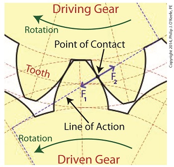
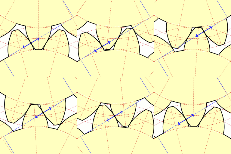
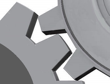
Last time we learned about forces generated when spur gear teeth mesh and move along a specific line of action. Today we’ll see them in movement. Looking at the illustration below it might appear that there are three teeth in contact, but this isn’t the case. As the gears rotate, only two teeth make contact at any given time, although the third tooth comes very close. The actual point of contact between the teeth is represented by a black dot on the illustration below. This is where two opposing forces, F1 and F2, meet. Now let’s animate the illustration to see how the line of action remains constant the entire time the gear teeth are in motion. By constant I mean that this imaginary line’s position and angle does not change relative to the gears throughout the course of their movement. In the animation, the point of contact moves along the line of action as the gears turn. Each tooth’s involute profile ensures that smooth contact is maintained along the faces and flanks of the gear teeth. The involute profile’s unique shape facilitates opposing teeth remaining in constant contact along the line of action for the duration of their movement together. If the gear tooth profile wasn’t involute in its shape, say for example it was square or triangular, the forces acting upon the meshed teeth during movement would vary in direction and intensity as a result of uneven contact between the teeth. For example, consider the square shaped tooth profile in the gear train below. As the gears rotate, the pointed tip of one tooth strikes the flat face of another. As they continue to turn, the two flat faces of the teeth slap together, then the pointed tip of one tooth will strike the flat face of the other tooth, and so forth. The result is movement that is jerky and destructive. There would be excessive vibration and wear and tear on the teeth, resulting in rapid gear tooth erosion and decreased efficiency overall. Next time we’ll introduce the gear ratio, a formula which allows us to alter the rotational speed of the driven gear in relation to that of the driving gear, something which comes in handy when designing things that require this differential.
_______________________________________ |
The History of Gears
Monday, December 23rd, 2013|
Could it be that after cave men invented the wheel they moved on to invent another circular object, the gear? Gear assemblies are found in a wide variety of applications, from tiny ones used inside wrist watches to massive ones found in aircraft carriers. No one knows for certain when gear technology was first employed, but we do know that gear driven machinery has been around since before the Industrial Revolution. As far back as the Renaissance we’ve documented their use within flour milling equipment and the first primitive clocks. Going even further back in time, Roman engineers are known to have developed a primitive gear driven odometer. It was attached to horse drawn cart wheels and the number of revolutions performed allowed the distance traveled to be calculated. In fact gears have been used far longer than scientists originally thought. In October of the year 1900 sponge divers stumbled upon an ancient Roman shipwreck at the bottom of the Aegean Sea near the Greek island of Antikythera. Inside this wreck they found mineral encrusted fragments of an artifact composed of a bronze alloy. This amazing discovery appeared to be a remarkably modern looking gear assembly which would come to be known as the Antikythera Mechanism.
Analysis of the Mechanism conducted over the last 100 years has revealed it to be a highly complex device. Still visible engraved inscriptions disclose it to be of Greek origin, dating back to about 100 BC. As such it’s the oldest known complex gear driven mechanism in the world. Prior to its discovery it was thought that mechanisms of its kind were not made until 1400 AD. As to the purpose it served, that remains a subject of controversy, since many of its parts are missing.
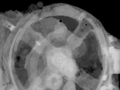
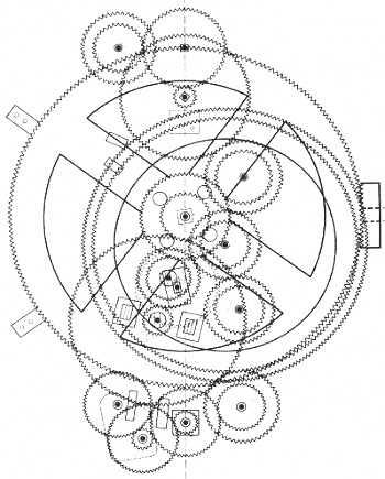
The X-ray image reveals some of the Mechanism’s hidden complexity. Based on detailed examination of these images coupled with engineering analysis, it’s theorized by scientists that the mechanism may have been configured as illustrated below.
Since there’s no evidence that ancient Greeks possessed motors, such as those used in modern clocks, some scientists believe that the gears in the Mechanism were set into motion by simply turning a hand crank. Others believe that the arrangement and size of the gears indicate that the Mechanism’s movement is analogous to planetary motion within our solar system. They theorize further that it may have been used to calculate the positions of the Sun, Moon, and other celestial bodies. Next time we’ll fast forward to present day to familiarize ourselves with the basic terminology of gears and then later see how they’re used in modern devices.
________________________________________ |
