|
Last time we began our discussion on velocity by focusing on one of its aspects, distance, and we calculated Earth’s orbital distance around the sun to be 5,816,023,200 miles. Today we’ll focus on velocity’s other aspect, time. Together, these aspects will allow us to solve for Earth’s orbital velocity, aka speed. When early astronomers monitored Earth’s journeys, they found it took exactly one year for it to complete its orbit around the sun. They combined this fact with Earth’s orbital travel distance of 5,816,023,200, or 9.36 × 10¹¹ meters — meters being the unit of measurement most often used in scientific computations — and solved for Earth’s orbital velocity as follows, v = 9.36 × 10¹¹ meters ÷ 1 year = 9.36 × 10¹¹ meters per year The scientific notation of 9.36 × 10¹¹ equates to 936,000,000,000 meters, a large and unruly number to work with. We can simplify things further by breaking this number down into units of meters per second, which will then allow us to arrive at Earth’s velocity in terms of miles per hour, something most Earthlings can relate to. One meter per second is equal to 2.237 miles per hour, and there are 31,536,000 seconds in one year, so breaking Earth’s orbital velocity down into meters per second we arrive at, v = 9.36 × 10¹¹ meters ÷ 31,536,000 seconds = 29,680 meters per second v = (29,680 meters per second) × (2.237 mph/m/sec) = 66,394 miles per hour Yes, it’s true, Earth whips around the sun at warp speed. Our fastest man made rockets only achieve speeds of about 25,000 miles per hour. Earth beats them two-to-one!
Now that we know Earth’s orbital velocity, we have everything we need to calculate the gravitational force exerted on Earth by the sun. We’ll do that next time.
____________________________________
|
Posts Tagged ‘mechanical engineering expert’
Earth’s High Speed Race Around the Sun
Tuesday, July 28th, 2015
What Determines Rate of Fall?
Thursday, September 4th, 2014|
Picture yourself holding a feather in one hand, a hammer in the other. Your buddy has bet you that if you simultaneously drop them, the hammer will hit the ground first, and he’s got a beer riding on it. This exact experiment was performed in 1971 by Apollo 15 Astronauts David Scott and Jim Irwin when they landed on the moon. We’ll tell you how it turned out later, but first let’s review the history behind the study of falling objects. Aristotle, the ancient Greek philosopher, would have bet with your buddy. Back in the 4th Century BC he developed a theory of gravity to explain the physics behind falling objects. He asserted that the heavier the object, the faster it will fall. His theory seems intuitively obvious on its face, but although Aristotle was a great philosopher, he was a lousy scientist. He never ran tests to actually prove his theory. Nevertheless, it was accepted by academics of his time, and it remained the theory of choice until Galileo came along in the 16th Century. Galileo was a scientist, and he came up with his own theory concerning falling objects. He believed that all falling objects continue to accelerate, picking up speed as they fall, and that this rate of acceleration is the same for all objects, regardless of their weight or density. The story goes that in 1589, at the age of 25, young Galileo attempted to prove his theory by climbing to the top of the Leaning Tower of Pisa with two balls in hand, one large and heavy, the other small and light. He dropped them at the same time, and guess what happened?
Both balls hit the ground at almost the same time. They would have hit the ground at precisely the same moment had there been no air resistance, a subject which will be discussed at length later in this blog series. Because Galileo’s experiment was subject to the dense atmosphere of Earth, the influence of air resistance prevented him from proving his theory correct, however he did manage to prove Aristotle’s theory wrong because the balls did not strike the ground at significantly different times. We’ll see how the astronauts’ experiment turned out next time.
_______________________________________
|

Equating Torques and Pitch Circle Radii Within a Gear Train
Thursday, May 29th, 2014|
Last time we developed torque equations for the driving and driven gears within a simple gear train. They are, T1 = D1 × F T2 = D2 × F where, T1 and T2 are the driving and driven gear torques, D1 and D2 are the driving and driven gear pitch radii, and F is the resultant Force vector, the common factor between the two equations.
Now we’ll combine these two equations relative to F to arrive at a single equation which equates the torques and pitch circle radii of the driving and driven gears in the gear train. This type of computation is commonly used to design gear trains to ensure they perform at a given level. As a first step we’ll use algebra to rearrange terms and place the two equations equal to F. First we’ll do it for the driving gear, dividing both sides of the equation by the pitch circle radius, D1. T1 ÷ D1 = D1 ÷ D1 × F T1 ÷ D1= 1 × F F = T1 ÷ D1 In a similar fashion, we’ll do it for the driven gear by dividing both sides of the equation by the pitch circle radius, D2. T2 = D2 × F → F = T2 ÷ D2 Since F is the common term between the two equations, we can set them up as equal to each other, F = T1 ÷ D1 = T2 ÷ D2 which means that, T1 ÷ D1 = T2 ÷ D2 Next time we’ll see how to use this equation to manipulate our gear train so that it acts as a torque converter by increasing T2 with respect to T1 and the ratio of D1 to D2, thus providing a mechanical advantage to the electric motor the gear train is attached to. _______________________________________ |

Distance and Force Vectors of a Simple Gear Train
Monday, May 5th, 2014|
Last time we examined how torque and force are created upon the driving gear within a simple gear train. Today we’ll see how they affect the driven gear.
Looking at the gear train illustration above, we see that each gear has both distance and force vectors. We’ll call the driving gear Distance vector, D1, and the driven gear Distance vector, D2. Each of these Distance vectors extend from pivot points located at the centers of their respective gear shafts. From there they extend in opposite directions until they meet at the line of action, the imaginary line which represents the geometric path along which Force vectors F1 and F2 are aligned. As we learned last time, the Force vector, F1, results from the torque that’s created at the pivot point located at the center of the driving gear. This driving gear is mounted on a shaft that’s attached to an electric motor, the ultimate powering source behind the torque. F1 follows a path along the line of action until it meets with the driven gear teeth, where it then exerts its pushing force upon them. It’s met by Force vector F2, a resisting force, which extends along the same line of action, but in a direction opposite to that of F1. These two Force vectors butt heads, pushing back against one another. F2 is essentially a negative force manifested by the dead weight of the mechanical load of the machinery components resting upon the shaft of the driving gear. Its unmoving inertia resists being put into motion. In order for the gears in the gear train to turn, F1 must be greater than F2, in other words, it must be great enough to overcome the resistance presented by F2. With the two Force vectors pushing against each other along the line of action, the angle ϴ between vectors F2 and D2, is the same as the angle ϴ between F1 and D1. Next time we’ll use the angular relationship between these four vectors to develop torque calculations for both gears in the gear train. _______________________________________ |

Spur Gears In Motion
Wednesday, February 12th, 2014|
Last time we learned about forces generated when spur gear teeth mesh and move along a specific line of action. Today we’ll see them in movement. Looking at the illustration below it might appear that there are three teeth in contact, but this isn’t the case. As the gears rotate, only two teeth make contact at any given time, although the third tooth comes very close. The actual point of contact between the teeth is represented by a black dot on the illustration below. This is where two opposing forces, F1 and F2, meet.
Now let’s animate the illustration to see how the line of action remains constant the entire time the gear teeth are in motion. By constant I mean that this imaginary line’s position and angle does not change relative to the gears throughout the course of their movement.
In the animation, the point of contact moves along the line of action as the gears turn. Each tooth’s involute profile ensures that smooth contact is maintained along the faces and flanks of the gear teeth. The involute profile’s unique shape facilitates opposing teeth remaining in constant contact along the line of action for the duration of their movement together. If the gear tooth profile wasn’t involute in its shape, say for example it was square or triangular, the forces acting upon the meshed teeth during movement would vary in direction and intensity as a result of uneven contact between the teeth. For example, consider the square shaped tooth profile in the gear train below.
As the gears rotate, the pointed tip of one tooth strikes the flat face of another. As they continue to turn, the two flat faces of the teeth slap together, then the pointed tip of one tooth will strike the flat face of the other tooth, and so forth. The result is movement that is jerky and destructive. There would be excessive vibration and wear and tear on the teeth, resulting in rapid gear tooth erosion and decreased efficiency overall. Next time we’ll introduce the gear ratio, a formula which allows us to alter the rotational speed of the driven gear in relation to that of the driving gear, something which comes in handy when designing things that require this differential.
_______________________________________ |


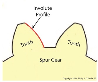
Spur Gear Tooth Geometry and the Involute Curve
Sunday, January 19th, 2014|
Last time we learned how spur gears mesh together to form a gear train and we examined a train consisting of just two gears, one being the driving gear, the other the driven gear. Today we’ll take a look at the geometry behind the smooth functioning of modern spur gear teeth when we identify their peculiar shape to be that of an involute curve. The curved profile of spur gear teeth conforms to a type of mathematical curve found in geometry known as an involute. The involute profile of a spur gear tooth is shown in red below. The mathematical notion of the involute was first presented in 1673 by Dutch mathematician Christiaan Huygens, in his book, Horologium Oscillatorium. Huygens’ book presents his studies on clock pendulums and the applied mathematics he used in an effort to predict their often erratic motion on ships at sea. His book ultimately dealt with far more than this, resulting in a treatise on the mathematical properties of the involutes of curves. To see how an involute curve is formed, we’ll conduct a simple experiment. One end of string is attached with a tack to a circular object, like the yellow rod shown in the following illustration. The other end of string has a red ball attached to it.
 Forming An Involute Curve If we grab the ball and pull the string taught while wrapping the string around the rod, the ball’s path will form an involute curve due to the incremental shortening of the string that occurs as it wraps around the rod. Next time we’ll see how the involute profile of gear teeth contributes to efficient mechanical energy transmission in gear trains. _______________________________________ |

Gear Trains
Monday, January 13th, 2014|
Last time we covered the basic terminology of spur gears. Today we’ll see how they interact with one another to form a gear train, such as the one depicted below.
 Meshing Spur Gears Form A Gear Train A gear train is formed when the teeth of two or more gears mesh and work together for the purpose of powering a mechanical device. A gear train can consist of as little as two gears, but trains can be so large as to contain dozens of gears, depending on the complexity of the device they are powering. But no matter how many gears are employed, there are certain key features that are shared by every gear train assembly. First, one gear within the train must be attached to a shaft rotated by a source of mechanical energy, such as an engine or electric motor. This gear is called the driving gear. The second requirement of a gear train is that at least one gear other than the driving gear is mounted to the shaft of a rotating machine part. This gear is called the driven gear.
 Locomotive Gear Train Consisting Of Two Gears The illustration above shows an exploded view of a locomotive gear train assembly consisting of two gears. The driving gear is mounted to the shaft of an electric traction motor. The driven gear is mounted to the locomotive’s axle. When a motor is attached to the axle, the two gears mesh together. The traction motor converts electrical energy into mechanical energy, which is supplied to the driving gear via the spinning motor’s shaft. The teeth of the driving gear then transmit the motor’s mechanical energy to the teeth of the driven gear, which then turn the locomotive’s wheels. It’s just one of countless operations that can be performed with gear train assemblies. Next time we’ll examine the geometry behind modern spur gear tooth design. _______________________________________ |


