|
Did you ever have someone you considered to be a great friend and then things suddenly went bad between you? One day you’re chums and then the magic fades, soon to disappear? Sound like some marriages you’ve heard about? Well, it wasn’t too long ago that coal was considered to be America’s affordable answer to our fuel needs. It was a friend of grand proportions, there when you needed it. It remains an abundant resource, so abundant in fact that according to the US Energy Information Administration (EIA) we are sitting on coal reserves so vast they can provide us with sufficient energy to get us through the next 250 years at current rates of consumption. It was for these reasons that electric utilities decided decades ago to use coal as the primary source of fuel to generate electricity, and as it stands now just over 50% of our electrical energy is generated by burning coal. So how did coal go from being friend to foe? Well, just as when you’ve known someone for awhile their “baggage” becomes more apparent, it eventually became apparent to Americans that burning coal comes with some nasty baggage of its own, known as byproducts. These unwelcome components of the burning/oxidation process were found in the plumes of smoke that billowed out of power plants’ smokestacks. So just what are these byproducts? Well, some of it is the same stuff that’s left over at the bottom of your barbecue grille after a cookout, and some of it comes with scientific names like sulfur dioxide (SO2), nitric oxide (NO), and nitrous oxide (N2O). Let’s look at these in more detail. Ash is the residue that’s left behind after coal is burned. Fly ash is a type of ash that is made up of some very light particles and it can get carried away by the hot gases coming off the fire in a power plant boiler. Some of those particles manage to leave the smokestack and enter the environment. Sulfur dioxide, or SO2, is formed when the sulfur in coal combines with oxygen in the air during burning. When the SO2 leaves the smokestack, it can combine with moisture in the atmosphere to form acid rain. Most of us know what acid rain is, but for those that don’t, acid rain does things like rust metal, dissolve marble monuments, and in general disrupt the balance of Earth’s eco systems. Nitric oxide, NO, and nitrous oxide, N2O, are chemical compounds composed of nitrogen and oxygen that fall into the group commonly referred to as NOx, pronounced “knocks.” NOx is formed when nitrogen and oxygen in the air combine at the high temperatures released when coal is burned inside power plant furnaces. NOx is bad because its compounds are key ingredients in the formation of both acid rain and smog. Over the last thirty years emissions of these byproducts have come under increasing scrutiny by federal and state regulators in their quest to curb them and their impact on our environment. As a result, electric utilities have had to comply with ever-tightening regulations. To comply, coals with lower sulfur content have been used, often brought in over very long distances from mines in the US and even foreign countries like Columbia. Utilities have also been installing expensive pollution control equipment in their coal fired power plants. But these changes make operations more expensive, eating into the utilities’ profits. Now we may not like the idea of utilities earning a profit, but this is a necessary reality to some extent in order to keep their business solvent. They’re not in it for the fun of it, after all. And I’m sure you guessed by now that the net result of the regulatory agencies’ mandates is that our electric bills just keep escalating. Now much of what lies behind the current unfavorable status of coal powered plants is that when operating on our native soil they have high visibility. We don’t like to be reminded of the negatives that accompany the production of energy. Put that same plant in another faraway country and the byproducts cease to be an issue. It’s happening over there after all, and we don’t have to be confronted with it. We neglect to remind ourselves that the earth’s atmosphere is for the most part a contained unit, and that means that what happens there is happening here, whether there happens to be on the other side of the globe or not. Next week we’ll continue our explorations into coal, examining the impact of the low sulfur variety on electric utility power generation. _____________________________________________
|
Archive for June, 2010
Fossil Fuel, From Friend to Foe
Sunday, June 27th, 2010
CAD To The Rescue
Sunday, June 20th, 2010|
Remember Mike, the dad on The Brady Bunch, forever hunched over his drafting table while Alice, the housekeeper, regales him with yet another tale of Brady kids gone rambunctiously wrong? Although he seemed very attached to his mechanical pencil and rolls of architectural drawings, he’d have been far better off with a computer and CAD software. CAD, or Computer Aided Design, makes the life of architects, engineers, and designers of various sorts a whole lot easier. It’s been around for a few decades now, and its applications just keep getting broader. Once familiar with the workings of this software, one can produce technical diagrams in record time, and mistakes are just a delete button away from being eradicated. In fact, it’s very much like a word processor for graphics, not words. Nowadays, for all intents and purposes, the drafting table, pencils and rulers are pretty much extinct from usage by architects and engineers, much like The Brady Bunch television show. Remember the days of typewriters and carbon paper? If you do, you just dated yourself, because these haven’t been in general usage for quite some time. Word processing software and computers in general have relegated these instruments to become dusty on the shelves of historical museums. Why laboriously copy an object by hand, over and over again, when you can cut and paste your way to duplication perfection using CAD? There are even special features within CAD that allow for replication of a drawing detail in an array, meaning it is automatically replicated a specified number of times while being spaced precise distances apart along a straight line or circle. Let’s look at a simple example of how CAD makes our life so much easier. Figure l shows a single gear tooth, drawn in CAD. Figure 2 shows the tooth automatically replicated ten times and displayed in a circular array, each tooth a precise space away from its nearest neighbor. Figure 3 shows all of the gear teeth connected together with lines to form a completed drawing. Before the advent of CAD, an engineer would have had to replicate each gear tooth by hand using physical tools like a compass, pencil, and scale ruler. Figure 1 – A Single Gear Tooth Drawn With CAD
Figure 2 – A 10 Tooth Circular Array Created With CAD
Figure 3 – A Completed CAD Drawing of a 10 Tooth Gear
Another useful feature of CAD is how it can be used to annotate drawings, that is, put notes, labels, and dimensions on them. This nifty feature has rendered precise penmanship obsolete. Gone are the days when student engineers labored by hand and pencil to produce precisely the lettering and numbering conventions that are acceptable within their discipline. Poor penmanship could be disastrous to both the engineer’s career and the final product due to the difficulty it would present in reading and proper interpretation. CAD produces a level of uniformity never before possible, but of course one still needs to know how to spell! If you look back through my blog articles, you’ll see many diagrams that I created with CAD software, thus rendering complicated technical concepts easier to understand. Illustrations are most often easier to understand by the general population than the written word, and as one of my past blogs was titled, A Picture is Worth a Thousand of Them, “them” being words, of course. I also routinely use CAD software in other aspects of my profession to create everything from electrical schematics to flow charts, PowerPoint presentations slides, and engineering expert reports. _____________________________________________
|


Regenerative Brakes
Sunday, June 13th, 2010|
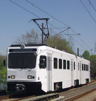
Have you ever been stranded on a subway car? The lights flickered wildly, then the odd humming sounds all came to an abrupt stop, and you sat there exchanging uncomfortable glances with your fellow passengers? “Hey, get this thing going! I’ve got an appointment to make!” someone shouts at the driver, sequestered in his cab. The trouble is, he, like the rest of the passengers, is equally helpless in this situation. You see, streetcars, subway cars, and light rail cars are all forms of electric railway cars, and when their source of electricity goes out, so do they. They’re similar to the diesel-electric locomotive we looked at last week because they use electric traction motors for propulsion, meaning to move forward. But their difference lies in the fact that electric rail cars don’t carry their own source of power and are entirely reliant on an external source, an electrical substation. See Figure 1 below.
Figure 1 – Electric Railway Car Propulsion System This substation performs the task of taking the power provided by an electric utility power plant and converting it into a form of power that the electric rail car can use to operate its traction motors. The two are connected via a trolley wire and the two rails that the car runs on. The railway car has a spring-loaded arm called a pantograph on its roof that touches the trolley wire, allowing electrical current to flow into a speed control system housed under the car. This speed control system performs the task of varying the flow of electrical current to the traction motors, enabling the car to move, before it eventually exits the motor through its wheels, then back to the substation where it originated, thus completing an electrical circuit. Many newer electric railway cars couple a regenerative braking system with a mechanical one. Their operation is similar in nature to a dynamic braking system where the traction motors are turned into generators. The difference is that with regenerative braking systems the current from the traction motors is sent to the trolley wire through the pantograph as shown in Figure 2 below.
Figure 2 – An Electric Railway Car Using Regenerative Brakes This diagram shows the railcar generating electricity, but it may not be so obvious how its motion is made to slow down, after all, we see no resistor grids like we did in last week’s illustration of a dynamic braking system. So how does it stop? The trick here is that there are other cars running on the rail line at the same time which are using electrical current to move forward. So what does this have to do with stopping it you ask? Let’s take a look at Figure 3 for clarification. Figure 3 – How Regenerative Brakes Help Save Power In this illustration we see that as Car A goes downhill and the operator applies the brakes, the regenerative brake will be caused to start pumping electrical current into the trolley wire. Now, if Car B is on the same rail line going up the other side of the hill, it will need power to climb that hill, and it will need to draw that power from the trolley wire by way of its pantograph. But instead of drawing all its electrical current from the substation, Car B will first draw off the current produced by nearby Car A, and only then will it draw the remainder of its power requirements from the substation. During this braking process the kinetic energy in Car A is converted into electrical energy by its traction motors. Then Car B uses its own traction motors to convert the electrical energy drawn from Car A into mechanical energy, enabling it to climb the hill. Car B has effectively robbed Car A of its energy, so Car A slows down. As we discovered last week during our discussion of dynamic brakes, regenerative brakes become ineffective below a certain minimum speed. This is the reason that electric rail cars need mechanical brakes to complete the job of stopping. We see that the regenerative braking process is actually quite green. It allows for electrical energy that would normally be wasted as heat energy escaping into the atmosphere to be converted into useful energy, taking a significant chunk out of the demand for new energy off of substations. It also helps the electric railway to save money when it comes time to paying the electric bills. You may have noticed a copyright symbol and my name included in this week’s illustrations. That’s because it has recently come to my attention that many of my readers are unaware that I am the CAD (Computer Aided Design) artist who creates the illustrations featured in most of my blogs. CAD is a useful tool in explaining difficult technical subject matter, which is precisely why I use it so often. Next week we’ll explore in more depth the benefits of using this tool.
_____________________________________________
|


Diesel Locomotive Brakes
Sunday, June 6th, 2010|
In the past few weeks we’ve taken a look at both mechanical and dynamic brakes. Now it’s time to bring the two together for unparalleled stopping performance. Have you ever wandered along a railroad track, hopping from tie to tie, daring a train to come roaring along and wondering if you could jump to safety in time? Many have, and many have lost the bet. That’s because a train, once set into motion, is one of the hardest things on Earth to bring to a stop. In this discussion, let’s focus on the locomotive. A large, six-axle variety is shown in Figure 1.
Figure 1 – A Six-Axle Diesel-Electric Locomotive These massive iron horses are known in the industry as diesel-electric locomotives, and here’s why. As Figure 2 shows, diesel-electric locomotives are powered by huge diesel engines. Their engine spins an electrical generator which effectively converts mechanical energy into electrical energy. That electrical energy is then sent from the generator through wires to electric traction motors which are in turn connected to the locomotive’s wheels by a series of gears. In the case of a six-axle locomotive, there are six traction motors all working together to make the locomotive move. So how do you get this beast to stop? Figure 2 – The Propulsion System In A Six-Axle Diesel-Electric Locomotive You probably noticed in Figure 2 that there are resistor grids and cooling fans. As long as you’re powering a locomotive’s traction motors to move a train, these grids and fans won’t come into play. It’s when you want to stop the train that they become important. That’s when the locomotive’s controls will act to disconnect the traction motor wires running from the electrical generator and reconnect them to the resistor grids as shown in Figure 3 below.
Figure 3 – The Dynamic Braking System In A Six-Axle Diesel Electric Locomotive The traction motors now become generators in a dynamic braking system. These motors take on the properties of a generator, converting the moving train’s mechanical, or kinetic, energy into electrical. The electrical energy is then moved by wires to the resistor grids where it is converted to heat energy. This heat energy is removed by powerful cooling fans and released into the atmosphere. In the process the train is robbed of its kinetic energy, causing it to slow down. Now you may be thinking that dynamic brakes do all the work, and this is pretty much true, up to a point. Although dynamic brakes may be extremely effective in slowing a fast-moving train, they become increasingly ineffective as the train’s speed decreases. That’s because as speed decreases, the traction motors spin more slowly, and they convert less kinetic energy into electrical energy. In fact, below speeds of about 10 miles per hour dynamic brakes are essentially useless. It is at this point that the mechanical braking system comes into play to bring the train to a complete stop. Let’s see how this switch from dynamic to mechanical dominance takes place. A basic mechanical braking system for locomotive wheels is shown in Figure 4. This system, also known as a pneumatic braking system, is powered by compressed air that is produced by the locomotive’s air pump. A similar system is used in the train’s railcars, employing hoses to move the compressed air from the locomotive to each car.
Figure 4 – Locomotive Pneumatic Braking System In the locomotive pneumatic braking system, pressurized air enters an air cylinder. Once inside, the air bears against a spring-loaded piston, as shown in Figure 4(a). The piston moves, causing brake rods to pivot and clamp the brake shoes to the locomotive’s wheel with great force, slowing the locomotive. When you want to get the locomotive moving again, you vent the air out of the cylinder as shown in Figure 4(b). This takes the pressure off the piston, releasing the force from the brake shoes. The spring in the cylinder is now free to move the shoes away from the wheel so they can turn freely. We have now returned to the situation present in Figure 2, and the locomotive starts moving again. Next week we’ll talk about regenerative braking, a variation on the dynamic braking concept used in railway vehicles like electric locomotives and subway trains. _____________________________________________
|


