| If you’ve ever read a book to a small child on the subject of food or digestion, you’ve probably come across the analogy that our stomachs are like a furnace and our digestive system much like an engine. We explain to the youngster that what we eat is important, because our body needs the right fuel in order to operate properly. If little Susie or Danny insisted on eating only candy day after day, their bodies would become weak and sick.
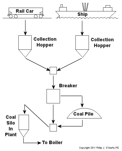
In much the same way a coal power plant is like a living organism, eating fuel in order to function. But instead of meats and vegetables, it eats coal, and the coal handling department of a power plant acts as a dinner table. It’s where the food is placed and prepared before it enters the diner’s mouth. The coal our power plants consume comes from one of two places, underground mines or strip mines. It all depends on the particular geology of the area from which the coal is harvested. According to the US Energy Information Administration, underground mines are more common in the eastern United States, while strip mines are more common in the western states. The coal from underground mines is excavated by means of shafts and tunnels which are dug deep beneath the earth’s surface in order to provide access to the buried coal deposits. In strip mines the deposits are just below the surface, so the topsoil is merely stripped away with heavy earthmoving machinery, like bulldozers, to reveal the coal. In both types of mining activity excavating machines and conveyors are required to remove the coal from the mine so it can be loaded for shipment to its ultimate destination. Once harvested, coal is shipped to power plants primarily by train, river barge, or ship. Its journey can cover thousands of miles. It culminates in delivery to a power plant, where it is unloaded by means of a huge piece of machinery called a rotary dumper. This machine is capable of grabbing onto 100 ton railcars and turning them upside down. The coal spills into a large collection hopper positioned next to the railroad track. If the coal has found its way to a plant located near a waterway, that means of transport was most likely have been made by flat barge or ship. In this case a large crane with a clamshell bucket is used for unloading. The crane drops its bucket into a pile of coal located within the ship’s hold, takes out a large bite, then hoists and dumps its contents into a large collection hopper next to the crane. To get an idea of how coal flows within the coal handling system of a power plant, let’s refer to the flow chart in Figure 1. Figure 1 – Schematic Diagram of the Coal Handling System Collection hoppers and have slanted bottoms which allow coal to easily spill out onto a conveyor belt. Within the plant coal is transported by means of conveyors into what’s known as a “breaker building.” This building lives up to its name because it contains a very large machine whose job it is to break the chunks of raw coal that have been harvested from mines into smaller chunks which the boiler can work with. Once broken down, the coal will go to one of two places, either directly into silos or coal bunkers in the power plant building for short term storage, or into an outside storage pile, usually a prominent feature of a power plant due to its formidable size. The coal pile can be several stories tall and much larger than a football field. It acts as a reserve supply should the regular delivery of coal be interrupted by labor strike, natural disaster, or equipment failure. When necessary, the coal is removed from the pile and sent into the plant to fill the coal silos. Coal from the silos is used to feed the power plant boilers. Next week we’ll continue to follow coal’s journey, on its way to arguably one of the most important pieces of equipment in a power plant, the boiler. _____________________________________________
|
Archive for January, 2011
Coal Power Plant Fundamentals
Sunday, January 23rd, 2011| Several years ago I was asked by power producers within the electric utility industry to write and then present a training course on the subject of coal power plant fundamentals. The finished product was a two day introductory course on the energy transformation process within a coal fired plant.
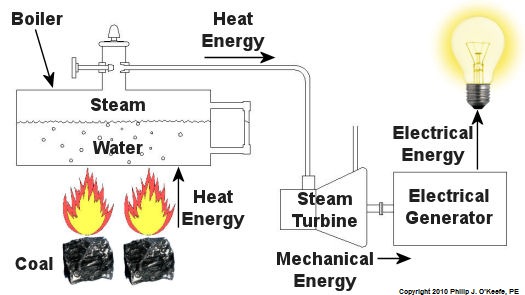
Since that time my seminar, entitled Coal Power Plant Fundamentals, has been presented to a variety of audiences, including Mirant Corporation, Platte River Power Authority, and Integrys Energy Group, Inc. Audience makeup has been diverse and has included equipment manufacturers, mining companies, power industry consultants, and regulatory agencies. This seminar, which I continue to present today in meeting rooms across the country, covers all major systems in a typical power plant, from coal handling when the coal first enters the plant, to its eventual end destination, the electrical switch yard which facilitates power transmission to customers. My Power Point presentation is embellished with ample illustrations, including photographs that I have taken during the course of my career and diagrams which I created using CAD, or Computer Aided Drawing software, one of which is featured below. In addition to the overhead slides, I provide a 150-page bound book which is distributed to seminar attendees. They use it to both follow along with my lecture and have a source of refresher material to take home with them. I’ve been told that having my illustrations in front of them makes a world of difference towards their understanding of the subject matter. The unique thing about my course is that it focuses on the simplified presentation of complex engineering concepts, much like my blogs do. Of course it always helps to have an engineering background or scientific background of sorts, but I wrote the course to accommodate understanding of the subject matter by individuals without any technical background. Accountants, salespersons, administrative staff, plant operating and maintenance workers, and journalists have all found the course to be easy to follow, interesting, and informative. So how do you get electricity from coal? To answer this question and give you a sampling of my seminar material let’s take a look at Figure 1. Figure 1 – The Coal Power Plant Energy Transformation Process Following along from left to right, the coal is first burned in order to transform the chemical energy which it contains into heat energy. That heat energy is then absorbed by water inside a nearby boiler, where it is converted into steam. The heat energy in the steam flows through a pipe into a steam turbine where it is again transformed, this time into mechanical energy that enables the turbine shaft to spin. The mechanical energy in the turbine is then transmitted by its shaft, enabling it to turn an electrical generator. And, finally, the mechanical energy is transformed by the generator into electrical energy for our usage. Simple process, right? Well, maybe, maybe not. My illustration certainly helped to simplify things, but there are a lot of details that were purposely omitted so as not to “muddy the waters.” It’s those details which have the potential to make things a lot more complicated, and next week we’ll begin to take a closer look at some of them. _____________________________________________ |
Strength of Materials – Poisson’s Ratio
Sunday, January 16th, 2011| Rubber bands, plastic food wrap, bandages that conform to knuckles and knees, where would we be without them? These are all fairly recent inventions, but their elastic properties were imagined far before they actually came into existence.
Around the turn of the 19th Century a mathematics genius by the name of Siméon Denis Poisson dabbled in higher level mathematics. He enjoyed working with calculus and probability theories and their applications, and his work eventually led to the discovery of his own special ratio, the “Poisson ratio.” Denoted today by the Greek letter “µ,” his discovery has a great deal to do with elasticity. In fact, much of his work evolved to become the modern study of engineering. If you’ll remember from last week’s blog, we talked about the elasticity of materials, including materials you generally wouldn’t think of as being elastic. In our steel rod example we saw that when you pull on the ends of a steel rod hard enough, you can actually stretch it and make it longer. But where does this extra length come from? According to Poisson’s ratio, as the rod lengthens, its diameter decreases proportionately. The rod’s increased length comes at the expense of its diameter. You can see this effect at work by repeatedly stretching that fat rubber band whose task it is to contain your bulging Sunday paper. The more you pull on it, the skinnier the rubber band becomes. It will eventually get to the point were its elastic properties have been so compromised it won’t even be able to hold together Monday’s paper. Over the decades that have passed since Poisson’s discovery a multitude of laboratory tests have been conducted to determine µ for a vast number of materials. These values have been duly tabulated in engineering reference books, doing away with the tedious task of conducting individualized experimentation by present day design engineers. Steel, for example, has a Poisson’s ratio of around 0.28, and this number is readily available in most strength of materials reference books. It’s pretty obvious why Poisson’s contribution is important to the world of engineering, but now let’s see how his ratio can be applied. Last week we saw that a 15-foot long, 2-inch diameter round steel rod stretches by 0.115 inches when it is pulled by a steady 60,000 pound force. Poisson’s ratio tell us that this results in an accompanying decrease in diameter, but by how much? To find out, we simply multiply the stretched length of the rod by Poisson’s ratio for steel (µ = 0.28). Plugging these numbers into an equation we see that the diameter decreases by: 0.115 inches × 0.28 = 0.032 inches This is approximately the thickness of nine sheets of paper. So if the rod was 2 inches in diameter before the 60,000 pound force was applied, its new diameter after application of the stretching force would be: 2 inches – 0.032 inches = 1.968 inches The change of .032 in the rod’s diameter may not seem like much, but in the world of machine parts it could mean the difference between parts fitting properly or becoming loose. This wraps up our short series on strengths of elastic materials. Next time we’ll move on to discuss coal power plant fundamentals, an arena in which many of the things we’ve been discussing take on real world meaning. _____________________________________________ |
Transformers – Electric Utility Power Savers
Sunday, January 2nd, 2011| Each day millions of Americans start their mornings with coffee, brewed in a coffee maker, and a microwaved breakfast. They flick on the light and exhaust fan before starting their showers and blow dry their hair afterwards. Each of these acts of modern living is a small miracle. And if you’re like most people you can’t see the power plant supplying the power to your modern conveniences from your home, and how the electricity travels from the plant to you isn’t too clear.
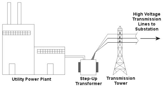
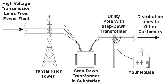
Truth is the process of supplying our homes with power isn’t as straightforward as you might think, and the actual transmission of that power isn’t straightforward at all. To begin with, the wires used in power lines are less than perfect conductors of electricity. Along any given length of wire there are all sorts of imperfections in the metal, and these tend to resist the flow of electrical current. These imperfections will always exist to some extent, even with the best manufacturing techniques and quality control, and the longer the power line, the more resistance the power flow will meet. The result is loss of electrical power. If there weren’t some kind of compensatory action at work to rectify this, your morning routine wouldn’t be nearly so smooth. To address the problem of power loss electric utilities use step-up transformers, similar to the one in Figure 1. This enables voltage produced by the generator at the plant to be raised to a higher voltage, in turn enabling it to travel longer distances and remain effective. Figure 1 – Electricity Leaving the Power Plant Goes Through a Step-Up Transformer For example, let’s say that an electric generator puts out 12,000 volts, and a step-up transformer raises that to 765,000 volts, enabling transmission to customers far away. If you will recall from last week’s blog, with electrical transformers, there is an inverse relationship between voltage and current. So, when a step-up transformer increases input voltage, it actually results in a lowering of electrical current. So how does this phenomenon aid in power transmission? Simply put, when there is less current flowing through the wires, there is an accompanying reduction in power loss over the long length of the transmission line. Let’s take a look at what happens when the power reaches our homes. Figure 2 shows a simplified distribution route from the power plant. Figure 2 – A Step-Down Transformer is Used to Supply Electric Utility Customers First, the higher voltage originating from the step-up transformer at the power plant is decreased by the use of a step-down transformer located in a substation many miles away at the other end of the transmission line. The use of this intermediary step-down transformer effectively lowers the voltage and at the same time raises the current at the other end of the line, the end where customers like you and I are waiting to use our hair dryers unimpeded. The path that the power follows is somewhat circuitous, but well planned out, with numerous strategically positioned distribution lines acting as the final leg of delivery. These distribution lines do what their name implies, they weave their way along streets and alleys, finally distributing electricity to customers. A step-down transformer located in a substation along the power transmission route allows this all to happen. It can readily convert the 765,000 volts being sent by the power plant to the 25,000 volts needed to feed distribution power lines. These, in turn, power individual homes, hospitals, etc. Now you obviously can’t plug a television into a 25,000 volt wall outlet located in your house, so another step-down transformer is required to temper it into power that’s both usable and safe. The one in our diagram is mounted on a nearby utility pole, and its job is to lower the 25,000 volts which it receives into a more manageable 240 and 120 volts, which is then fed into your home. That wraps up our series on electrical transformers. Perhaps the next time you flip that switch in your home, whether it be on your hair dryer, TV, or what have you, you’ll pause for a moment to reflect on the long path it has followed to make your life just a little bit easier. _____________________________________________
|
