| Ever take a peek inside the toaster while you’re waiting for the toast to pop up? If so, you would have noticed a bright orange glow. That glow is produced when the toasting wires heat up, which in turn creates a nice crusty surface on your bread or waffle. It’s the same phenomenon as when the filament inside an incandescent bulb glows. The light and heat produced in both these cases are the result of the Joule, pronounced “jewel,” effect at work.
To understand Joule heating, let’s first refresh our memories as to electrical current resistance. We learned previously that wire is not a perfect conductor, and as such resistance to flow is encountered. This resistance causes power to be lost along the length of wire, in accordance with this equation: Power Loss = I2 × R Where I is the electric current flowing through a wire, and R is the total electrical resistance of the wire. The power loss is measured in units of Joules per second, otherwise known as watts, “watt” denoting a metric unit of power. It is named after the famed Scottish mechanical engineer, James Watt, who is responsible for inventing the modern steam engine. A Joule is a metric unit of heat energy, named after the English scientist James Prescott Joule. He was a pioneer in the field of thermodynamics, a branch of physics concerned with the relationships between different forms of energy. Anyway, to see how the equation works, let’s look at an example. Suppose we have 12 feet of 12 AWG copper wire. We are using it to feed power to an appliance that draws 10 amperes of electric current. Going to our handy engineering reference book, we find that the 12 AWG wire has an electrical resistance of 0.001588 ohms per foot, “ohm” being a unit of electrical resistance. Plugging in the numbers, our equation for total electrical resistance becomes: R = (0.001588 ohms per foot) × 12 feet = 0.01905 ohms And we can now calculate power loss as follows: Power = I2 × R = (10 amperes)2 × (0.01905 ohms) = 1.905 watts Instead of using a 12 AWG wire, let’s use a smaller diameter wire, say, 26 AWG. Our engineering reference book says that 26 AWG wire has an electrical resistance of 0.0418 ohms per foot. So let’s see how this changes the power loss: R = (0.0418 ohms per foot) × 12 feet = 0.5016 ohms Power = I2 × R = (10 amperes)2 × (0.5016 ohms) = 50.16 watts This explains why appliances like space heaters and window unit air conditioners have short, thick power cords. They draw a lot of current when they operate, and a short power cord, precisely because it is short, poses less electrical resistance than a long cord. A thicker cord also helps reduce resistance to power flow. The result is a large amount of current flowing through a superhighway of wire, the wide berth reducing both the amount of power loss and the probability of dangerous Joule heating effect from taking place. Our example shows that the electric current flowing through the 12 AWG wire loses 1.905 watts of power due to the inconsistencies within the wire, and this in turn causes the wire to heat up. This is Joule heating at work. Joule heating of 50.16 watts in the thinner 26 AWG wire can lead to serious trouble. When using a power cord, heat moves from the copper wire within it, whose job it is to conduct electricity, and beyond, on to the electrical insulation that surrounds it. There the heat is not trapped, but escapes into the environment surrounding the cord. If the wire has low internal resistance and the amount of current flowing through it is within limits which are deemed to be acceptable, then Joule heating can be safely dissipated and the wire remains cool. But if the current goes beyond the safe limit, as specified in the American Wire Gauge (AWG) table for that type of wire, then overheating can be the result. The electrical insulation may start to melt and burn, and the local fire department may then become involved. That’s it for wire sizing and electric current. Next time we’ll slip back into the mechanical world and explore a new topic: the principles of ventilation. _____________________________________________ |
Posts Tagged ‘electrical safety’
Wire Size and Electric Current – Joule Heating
Sunday, March 20th, 2011Wire Size and Electric Current
Sunday, March 13th, 2011| Whether or not you live or work in a city, you are probably aware of rush hour traffic and how frustrating it can be. As a matter of fact, this traffic is the number one reason many choose to live within cities providing public transportation. Instead of watching the cars pile up in front of you, you can be checking your email or reading the paper. And no matter where you live, you’ve probably encountered a narrow one-lane road at some time. If this road were to be spotted with traffic lights and double parked cars, the resulting frustration would reach a new high, one which has you craving the freedom of a crowded three-lane expressway. At least there’s the possibility of movement there.
Generally, the wider the road and the fewer the impediments, the better traffic will flow. The problems presented by vehicular traffic are analogous to those present in electrical wires. For both, obstructions are impediments to flow. You see, the thicker the metal is in a wire, the more electrical current it can carry. But before we explore why, let’s see how electric wires are classified. If you’ve ever spent any time hanging around a hardware store looking at the goodies, you’ve probably come across wire gauge numbers, used to categorize wire diameter. American Wire Gauge (AWG) is a standardized wire gauge system, used in North American industry since the latter half of the 19th Century. Handy as it is, the AWG gauge numbering system seems to go against logic, because as a wire’s diameter increases, its gauge number decreases. For example, a wire gauge number of 8 AWG has a diameter of 0.125 inches, while a gauge number of 12 AWG has a diameter of 0.081 inches. To make things easier on those who need to know this type of information, wire diameter is tabulated for each AWG gauge number and readily available in engineering reference books. So what does this have to do with electric current? To begin with, the larger the AWG number, the less current it can safely carry. If we turn to an engineering reference book, and look up information relating to an 8 AWG insulated copper wire, we find that it can safely carry an electrical current of 50 amperes, while a 12 AWG insulated copper wire can safely carry only 25 amperes. This information allows us to make important and relevant design decisions regarding a myriad of things, from electrical wiring in electronic devices, to appliances, automobiles, and buildings. So, why are bigger wires able to carry more current? Well, as you’ve heard me say before, no wire is a perfect conductor of electricity, but some metals, take copper for instance, are better conductors than others, say steel. But even the best conductors are inherently full of impurities and imperfections that resist the flow of electricity. This electrical resistance acts much like traffic lights and double parked cars that impede the flow of traffic. The larger the diameter of the wire, the less electrical resistance is present. The logic here is simple. Wire that is larger allows more paths for electrical current to flow around impurities and imperfections. The congestion present in rush hour traffic results in travel delays and hot tempers, and heat is also present in electric wires that face resistance to electricity flow. If the resistance to electric current flow is high enough, it can cause overheating. Road rage within the wires is a possibility, and if the wires get hot enough, electrical insulation can melt and burn, creating a fire. Known as the “Joule heating” effect, this phenomenon is responsible for its share of building fires. We’ll learn more about Joule heating and how wires are sized to keep electrical current flow within safe limits next week. Until then, try to keep out of traffic. _____________________________________________
|
Transformers – Electric Utility Power Savers
Sunday, January 2nd, 2011| Each day millions of Americans start their mornings with coffee, brewed in a coffee maker, and a microwaved breakfast. They flick on the light and exhaust fan before starting their showers and blow dry their hair afterwards. Each of these acts of modern living is a small miracle. And if you’re like most people you can’t see the power plant supplying the power to your modern conveniences from your home, and how the electricity travels from the plant to you isn’t too clear.
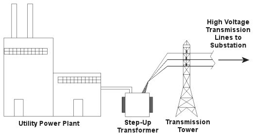
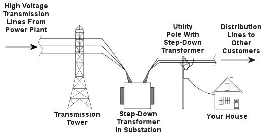
Truth is the process of supplying our homes with power isn’t as straightforward as you might think, and the actual transmission of that power isn’t straightforward at all. To begin with, the wires used in power lines are less than perfect conductors of electricity. Along any given length of wire there are all sorts of imperfections in the metal, and these tend to resist the flow of electrical current. These imperfections will always exist to some extent, even with the best manufacturing techniques and quality control, and the longer the power line, the more resistance the power flow will meet. The result is loss of electrical power. If there weren’t some kind of compensatory action at work to rectify this, your morning routine wouldn’t be nearly so smooth. To address the problem of power loss electric utilities use step-up transformers, similar to the one in Figure 1. This enables voltage produced by the generator at the plant to be raised to a higher voltage, in turn enabling it to travel longer distances and remain effective. Figure 1 – Electricity Leaving the Power Plant Goes Through a Step-Up Transformer For example, let’s say that an electric generator puts out 12,000 volts, and a step-up transformer raises that to 765,000 volts, enabling transmission to customers far away. If you will recall from last week’s blog, with electrical transformers, there is an inverse relationship between voltage and current. So, when a step-up transformer increases input voltage, it actually results in a lowering of electrical current. So how does this phenomenon aid in power transmission? Simply put, when there is less current flowing through the wires, there is an accompanying reduction in power loss over the long length of the transmission line. Let’s take a look at what happens when the power reaches our homes. Figure 2 shows a simplified distribution route from the power plant. Figure 2 – A Step-Down Transformer is Used to Supply Electric Utility Customers First, the higher voltage originating from the step-up transformer at the power plant is decreased by the use of a step-down transformer located in a substation many miles away at the other end of the transmission line. The use of this intermediary step-down transformer effectively lowers the voltage and at the same time raises the current at the other end of the line, the end where customers like you and I are waiting to use our hair dryers unimpeded. The path that the power follows is somewhat circuitous, but well planned out, with numerous strategically positioned distribution lines acting as the final leg of delivery. These distribution lines do what their name implies, they weave their way along streets and alleys, finally distributing electricity to customers. A step-down transformer located in a substation along the power transmission route allows this all to happen. It can readily convert the 765,000 volts being sent by the power plant to the 25,000 volts needed to feed distribution power lines. These, in turn, power individual homes, hospitals, etc. Now you obviously can’t plug a television into a 25,000 volt wall outlet located in your house, so another step-down transformer is required to temper it into power that’s both usable and safe. The one in our diagram is mounted on a nearby utility pole, and its job is to lower the 25,000 volts which it receives into a more manageable 240 and 120 volts, which is then fed into your home. That wraps up our series on electrical transformers. Perhaps the next time you flip that switch in your home, whether it be on your hair dryer, TV, or what have you, you’ll pause for a moment to reflect on the long path it has followed to make your life just a little bit easier. _____________________________________________
|
Arc Flash Dangers
Sunday, September 13th, 2009|
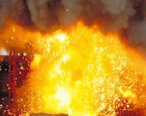
Imagine being hit by a bolt of lightning. Like lightning, an arc flash can unexpectedly release tremendous amounts of energy, resulting in serious injuries and even death. An arc flash is the result of a short circuit or electrical fault in energized equipment. Current flows through the air and creates an electrical arc, very much like the phenomenon of lightning. But unlike lightning, arc flash dangers are present in a myriad of circumstances that do not require storm conditions to manifest. Over 80% of electrically related injuries involve some type of arc flash. They can be caused by a wide variety of factors, including: equipment malfunctions, inadequate safety procedures, carelessness, lack of training, dropped tools, etc. The amount of energy released by the electrical arc depends on the amount of electrical current flowing through the arc and how long the current will flow before it is interrupted by a circuit breaker or fuse. The radiation released in an arc flash can be so intense and so rapid that it can instantly burn skin and ignite clothing. Temperatures at the electrical arc can rapidly climb to tens of thousands of degrees. At temps this extreme metal becomes liquid, then vaporizes, and the air surrounding the arc becomes superheated to approximately 30,000°F. The superheated air and metal vapor together expand with explosive force. This creates a dangerous and potentially lethal pressure wave of hot gas, molten metal droplets, and solid metal shards that can create burns and shrapnel wounds. The Occupational Safety and Health Administration (OSHA) requires employers to assess the workplace for arc flash hazards that are present or that are likely to be present. Assessment is done using standards developed by the National Fire Protection Association (NFPA) and the Institute of Electrical and Electronics Engineers (IEEE) to specifically address arc flash hazards. If hazards are identified, employers must mitigate risks by adhering to a six point compliance plan such as the following: 1. Implement a worker safety program with defined responsibilities. 2. Perform engineering studies that include calculations to determine the degree of arc flash hazards. These studies also must be updated when any changes to the electrical system are made by the employer or the electric utility. 3. Provide workers with the correct personal protective equipment (PPE) based on the study results. These PPE must then be maintained on site to protect workers. 4. Provide worker training on the hazards of arc flash. This training must be documented and workers must demonstrate proficiency through testing. Worker training must also be updated whenever any changes occur to the electrical system. 5. Provide appropriate tools for safe working. 6. Place conspicuous warning labels on equipment to warn workers about potential arc flash hazards. OSHA, like other government agencies, expects employers to keep up with regulations and take the necessary steps to remain compliant. For example, OSHA won’t send notices out to employers to inform them that they must implement an arc flash program in their plant. It’s up to the employers to know that and institute the necessary precautions on their own. It must also be noted that OSHA doesn’t walk employers through the steps of setting up an effective worker safety program. This means that workers can be exposed to arc flash hazards simply because their employer is ignorant of regulatory requirements and is operating based on misconceptions. Some workers are unfortunate enough to work for employers that don’t take potential dangers like arc flash seriously enough to implement an effective safety program. When their wakeup call comes, it’s often too late. _________________________________________________________________ Do you want to know more about implementing an effective Arc Flash Program in your facility? Phil O’Keefe developed and presents a 90-minute webinar entitled: “Arc Flash Program Fundamentals.” Contact him for more information about conducting this webinar for your organization. |


