|
Last time we introduced Gaspard-Gustave de Coriolis’ formula to compute kinetic energy. Today we’ll use it to determine the speed of descent, or velocity, of the coffee mug we’ve been watching closely in the last few blogs. To calculate the mug’s velocity, we must bear in mind physicist Julius Robert von Mayer’s assertion that all forms of energy are interrelated, and in fact interchangeable, because energy can neither be created nor destroyed, it can only change forms. For a refresher, see The Law of Conservation of Energy. Let’s now put a practical spin on this concept and apply it to our coffee mug’s free fall to the floor. Once again, de Coriolis’ formula, KE = ½ × m × v2 (1) where m is the mass of our falling object and v its velocity. The ½ is an unchanging, constant term that’s present due to the mathematical Rules of Integration governing integral calculus. Calculus and its derivations are beyond the scope of this blog, but if you’re interested in pursuing this, follow this link to, The Physics Hypertextbook – Kinetic Energy. According to von Mayer’s Law, at the precise instant before the mug hits the floor its kinetic energy, KE, is equal to the potential energy, PE, it possessed when it rested passively on the shelf. Stated another way, the instant before the mug makes contact with the floor, all its potential energy will have been converted into kinetic. The mug’s PE was calculated previously to be equal to 4.9 kg • meter2/second2. See Computing Potential Energy for a review. Knowing this, the mathematical relationship between the mug’s potential and kinetic energies is expressed as, PE = KE = 4.9 kg • meter2/second2 (2) By substituting this mathematical representation for KE into equation (1) we arrive at, 4.9 kg • meter2/second2 = ½ × m × v2 (3) We also know the mug’s mass, m, to be equal to 2.6 kilograms, so integrating that into the right side of equation (3) it becomes, 4.9 kg • meter2/second2 = ½ × ( 0.25kg) × v2 (4) That leaves the mug’s velocity, v2, as the only remaining unknown term. We’ll use algebra to isolate this variable by dividing both sides of equation (4) by ½ × ( 0.25kg). (4.9 kg • meter2/second2) ÷ [½ × ( 0.25kg)] = v2 39.20 meter2/second2 = v2 Finally, we’ll take the square root of the equation to place it in terms of v. 6.26 meters/second = v The mug’s velocity an instant before impact equates to 6.26 meters/second, or almost 21 feet per second. Next time we’ll discuss a metric unit used to measure energy known as the Joule and discover the man behind it. Copyright 2015 – Philip J. O’Keefe, PE Engineering Expert Witness Blog ____________________________________ |
Posts Tagged ‘physics’
Calculating Velocity — de Coriolis’ Kinetic Energy Formula
Monday, September 28th, 2015Calculation of the Effect of Machines — How to Calculate Kinetic Energy
Friday, September 18th, 2015|
Last time we introduced kinetic energy as the energy of movement. Today we’ll see how to calculate it, using French mathematician Gaspard-Gustave de Coriolis’ formula as set out in his textbook, Calculation of the Effect of Machines. We’ll then apply his formula to our example of a coffee mug falling from its shelf. Gaspard-Gustave de Coriolis’ book presented physics concepts, specifically the study of mechanics, in an accessible manner, without a lot of highbrow theory and complicated mathematics. His insights made complicated subjects easy to understand, and they were immediately put to use by engineers of his time, who were busily designing mechanical devices like steam engines during the early stages of the Industrial Revolution. Within its pages the mathematics of kinetic energy was presented in the scientific form that persists to present day. That formula is, KE = ½ × m × v2 where m is the moving object’s mass and v its velocity. In the case of our coffee mug, its kinetic energy will be zero so long as it remains motionless on the shelf. A human arm had lifted it to its perch against the force of gravity, thereby investing it with gravitational potential energy. If the mug was sent freefalling to the ground by the mischievous kitty, its latent potential energy would be realized and converted into the kinetic energy of motion. To illustrate, let’s say a mug with a mass equal to 0.25 kg rests on a shelf 2 meters above the floor. Its potential energy would then be equal to 4.9 kg • meter2/second2, as was computed in our previous blog, Computing Potential Energy. Once kitty nudges the mug from its perch and it begins to fall, its latent gravitational potential energy begins a conversion process from potential to kinetic energy. It will continue to convert into an amount of kinetic energy that’s precisely equal to the mug’s potential energy while at rest on the shelf, that is, 4.9 kg • meter2/second2. Upon impact with the floor, all the mug’s gravitational potential energy will have been converted into kinetic energy. Next time we’ll apply the Law of Conservation of Energy to the potential and kinetic energy formulas to calculate the mug’s velocity as it freefalls to the floor. Copyright 2015 – Philip J. O’Keefe, PE Engineering Expert Witness Blog ____________________________________
|
The Gear Train Tradeoff
Tuesday, August 5th, 2014|
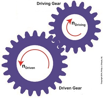
We’ve learned several methods to increase the torque of an electric motor through our series of articles on gear trains. One way is to attach a gear train to the motor’s shaft, a relatively simple thing to do. Today we’ll begin our exploration into how this method involves a tradeoff. It comes at the cost of speed. We’ll begin our examination of the tradeoff at play by linking together key elements learned through past blogs on the subject of gear trains. We’ll revisit those lessons through flashbacks. The first flashback we’ll make is to a blog entitled, Gear Ratio Formulas. There we learned that within a simple gear train consisting of two gears, the type most commonly employed to manipulate a motor’s torque, the ratio between the two gears, R, is relative to the ratio of their gear teeth, N. N is determined by the number of teeth each gear has in combination with the speeds, n, that each gear is going: R = NDriven ÷ NDriving = nDriving ÷ nDriven (1) The second flashback we’ll make is to a blog entitled, The Methodology Behind Gear Train Torque Conversions, in which we learned that the ratio of the torque, T, that exists between the gears is relative to the ratio of their respective pitch diameters, D: TDriving ÷ TDriven = DDriving ÷ DDriven (2) The tradeoff we’ve been alluding to comes in when gear speed, nDriven, represented in equation (1), is decreased, which results in an increase to TDriven in equation (2). But in order to see this we’ve got to somehow link the two equations together. In their present form there’s no common link between them. Or is there? There actually is an indirect link between the two equations, which comes by way of the torque equation presented in another past blog. The third flashback we’ll make is to the blog discussing that subject, which is entitled, The Relationship Between Torque and Horsepower. Using facts presented in that blog, the torque equations for our two gears become: TDriving = [HPDriving ÷ nDriving] × 63,025 (3) TDriven = [HPDriven ÷ nDriven] × 63,025 (4) Where’s the link between equations (1) and (2)? To answer that question we must reference a physics law known as The Law of Conservation of Energy . It states that the energy flowing from one gear to another within a gear train remains constant. Energy equates to horsepower, HP, in equations (3) and (4). So if the horsepower flowing through the gears is equal, our working equation becomes: HPDriving = HPDriven (5) Next time we’ll see how equation (5) is key to linking together equations (1) and (2) by way of equations (3) and (4). In so doing we’ll disclose the tradeoff to using gear trains. _______________________________________
|
Torque Formula Symplified
Wednesday, April 2nd, 2014|
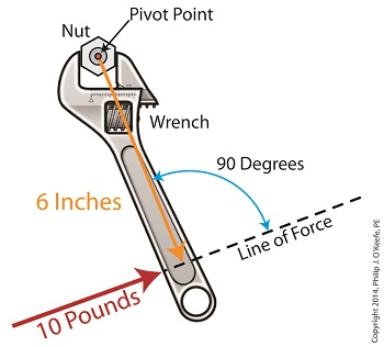
Last time we introduced the mathematical formula for torque, which is most simply defined as a measure of how much a force acting upon an object causes that object to rotate around a pivot point. When manipulated, torque can produce a mechanical advantage in gear trains and tools, which we’ll see later. The formula is: Torque = Distance × Force × sin(ϴ) We learned that the factors Distance and Force are vectors, and sin(ϴ) is a trigonometric function of the angle ϴ which is formed between their two vectors. Let’s return to our wrench example and see how the torque formula works. Vectors have both a magnitude, that is, a size or extent, and a direction, and they are typically represented in physics and engineering problems by straight arrows. In our illustration the vector for distance is represented by an orange arrow, while the vector for force is represented by a red arrow. The orange distance vector has a magnitude of 6 inches, while the red force vector has a magnitude of 10 pounds, which is being supplied by the user’s arm muscle manipulating the nut. That muscle force follows a path from the arm to the pivot point located at the center of the nut, a distance of 6 inches. Vector arrows point in a specific direction, a direction which is indicative of the way in which the vectors’ magnitudes — in our case inches of distance vs. pounds of force — are oriented with respect to one another. In our illustration the orange distance vector points away from the pivot point. This is according to engineering and physics convention, which dictates that, when a force vector is acting upon an object to produce a torque, the distance vector always points from the object’s pivot point to the line of force associated with the force vector. The angle, ϴ, that is formed between the two vectors in our example is 90 degrees, as measured by any common, ordinary protractor. Next we must determine the trigonometric value for sin(ϴ). This is easily accomplished by simply entering “90” into our calculator, then pressing the sin button. An interesting fact is that when the angle ϴ ranges anywhere between 0 and 90 degrees, the values for sin(ϴ) always range between 0 and 1. To see this in action enter any number between 0 and 90 into a scientific calculator, then press the sin button. For our angle of 90 degrees we find that, sin(90) = 1 Thus the formula for torque in our example, because the sin(ϴ) is equal to 1, simply becomes the product of the magnitudes of the Distance and Force vectors: Torque = Distance × Force × sin(90) Torque = Distance × Force × 1 Torque = Distance × Force Next time we’ll insert numerical values into the equation and see how easily torque can be manipulated. _______________________________________ |
Vectors, Sin(ϴ), and the Torque Formula
Wednesday, March 26th, 2014|
Last time we introduced a physics concept known as torque and how it, together with modified gear ratios, can produce a mechanical advantage in devices whose motors utilize gear trains. Now we’ll familiarize ourselves with torque’s mathematical formula, which involves some terminology, symbols, and concepts which you may not be familiar with, among them, vectors, and sin(ϴ). Torque = Distance × Force × sin(ϴ) In this formula, Distance and Force are both vectors. Generally speaking, a vector is a quantity that has both a magnitude — that is, any measured quantity associated with a vector, whether that be measured in pounds or inches or any other unit of measurement — and a direction. Vectors are typically represented graphically in engineering and physics illustrations by pointing arrows. The arrows are indicative of the directionality of the magnitudes involved. Sin(ϴ), pronounced sine thay-tah, is a function found within a field of mathematics known as trigonometry , which concerns itself with the lengths and angles of triangles. ϴ, or thay-tah, is a Greek symbol used to represent the angle present between the Force and Distance vectors as they interact to create torque. The value of sin(ϴ) depends upon the number of degrees in the angle ϴ. Sin(ϴ) can be found by measuring the angle ϴ, entering its value into a scientific calculator, and pressing the Sin button. We’ll dive into the math behind the vectors next time, when we return to our wrench and nut example and apply vector force quantities.
_______________________________________ |
Achieving Mechanical Advantage Through Torque
Wednesday, March 19th, 2014|
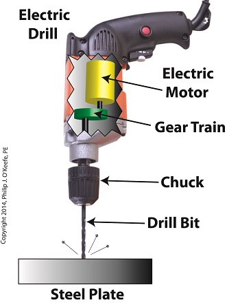
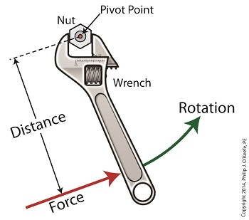
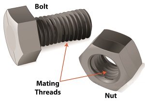
Last time we saw how gear train ratios allow us to change the speed of the driven gear relative to the driving gear. Today we’ll extend this concept further and see how gear trains are used to amplify the mechanical power output of small motors and in so doing create a mechanical advantage, an advantage made possible through the physics of torque. Below is an ordinary electric drill. Let’s see what’s inside its shell. There’s a whole lot of mechanical advantage at work here, giving the drill’s small motor the ability to perform big jobs. A motor and gear train are housed within the drill itself. The motor shaft is coupled to the chuck shaft via the gear train, and by extension, the drill bit. A chuck holds the drill bit in place. It’s the drill’s gear train that provides the small motor with the mechanical advantage necessary for this hand-held power tool to perform the big job of cutting through a thick steel plate. If the gear train and its properly engineered gear ratio weren’t in place and the chuck’s shaft was connected directly to the motor shaft, the motor would be overwhelmed and would stall or become damaged. Either way, the work won’t get done. To understand how operations like these can be performed, we must first familiarize ourselves with the physics concept of torque. Torque allows us to analyze the rotational forces acting upon rotating objects, such as gears in a gear train and wrenches on nuts and bolts. Manipulating torque allows us to achieve a physical advantage when rotating objects around a pivot point. Let’s illustrate this by using a wrench to turn a nut. The nut is fastened to the bolt with threads, interconnecting spiral grooves formed on both the inside of the nut and the outside of the bolt. A wrench is used to loosen and tighten the nut by rotating it on its mating threads. The nut itself rotates about a pivot point which lies at its center. When you use your arm to manipulate the wrench you apply force, a force which is transmitted at a distance from the pivot point. This in turn creates a torque on the nut. In other words, torque is a function of the force acting upon the handle relative to its distance from the pivot point at the center of the nut. Torque can be increased by changing one or both of its acting factors, force and distance. We’ll see how next time when we examine the formula for torque and manipulate it so that a weak arm can loosen even the tightest nut. _______________________________________ |
Wire Size and Electric Current – Joule Heating
Sunday, March 20th, 2011| Ever take a peek inside the toaster while you’re waiting for the toast to pop up? If so, you would have noticed a bright orange glow. That glow is produced when the toasting wires heat up, which in turn creates a nice crusty surface on your bread or waffle. It’s the same phenomenon as when the filament inside an incandescent bulb glows. The light and heat produced in both these cases are the result of the Joule, pronounced “jewel,” effect at work.
To understand Joule heating, let’s first refresh our memories as to electrical current resistance. We learned previously that wire is not a perfect conductor, and as such resistance to flow is encountered. This resistance causes power to be lost along the length of wire, in accordance with this equation: Power Loss = I2 × R Where I is the electric current flowing through a wire, and R is the total electrical resistance of the wire. The power loss is measured in units of Joules per second, otherwise known as watts, “watt” denoting a metric unit of power. It is named after the famed Scottish mechanical engineer, James Watt, who is responsible for inventing the modern steam engine. A Joule is a metric unit of heat energy, named after the English scientist James Prescott Joule. He was a pioneer in the field of thermodynamics, a branch of physics concerned with the relationships between different forms of energy. Anyway, to see how the equation works, let’s look at an example. Suppose we have 12 feet of 12 AWG copper wire. We are using it to feed power to an appliance that draws 10 amperes of electric current. Going to our handy engineering reference book, we find that the 12 AWG wire has an electrical resistance of 0.001588 ohms per foot, “ohm” being a unit of electrical resistance. Plugging in the numbers, our equation for total electrical resistance becomes: R = (0.001588 ohms per foot) × 12 feet = 0.01905 ohms And we can now calculate power loss as follows: Power = I2 × R = (10 amperes)2 × (0.01905 ohms) = 1.905 watts Instead of using a 12 AWG wire, let’s use a smaller diameter wire, say, 26 AWG. Our engineering reference book says that 26 AWG wire has an electrical resistance of 0.0418 ohms per foot. So let’s see how this changes the power loss: R = (0.0418 ohms per foot) × 12 feet = 0.5016 ohms Power = I2 × R = (10 amperes)2 × (0.5016 ohms) = 50.16 watts This explains why appliances like space heaters and window unit air conditioners have short, thick power cords. They draw a lot of current when they operate, and a short power cord, precisely because it is short, poses less electrical resistance than a long cord. A thicker cord also helps reduce resistance to power flow. The result is a large amount of current flowing through a superhighway of wire, the wide berth reducing both the amount of power loss and the probability of dangerous Joule heating effect from taking place. Our example shows that the electric current flowing through the 12 AWG wire loses 1.905 watts of power due to the inconsistencies within the wire, and this in turn causes the wire to heat up. This is Joule heating at work. Joule heating of 50.16 watts in the thinner 26 AWG wire can lead to serious trouble. When using a power cord, heat moves from the copper wire within it, whose job it is to conduct electricity, and beyond, on to the electrical insulation that surrounds it. There the heat is not trapped, but escapes into the environment surrounding the cord. If the wire has low internal resistance and the amount of current flowing through it is within limits which are deemed to be acceptable, then Joule heating can be safely dissipated and the wire remains cool. But if the current goes beyond the safe limit, as specified in the American Wire Gauge (AWG) table for that type of wire, then overheating can be the result. The electrical insulation may start to melt and burn, and the local fire department may then become involved. That’s it for wire sizing and electric current. Next time we’ll slip back into the mechanical world and explore a new topic: the principles of ventilation. _____________________________________________ |


