|
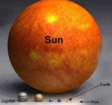
Last time we calculated the sun’s force of gravity acting upon Earth. It was the final unknown quantity within Newton’s equation to determine the mass of the sun, an equation we’ve been working with for some time now. Today we’re set to discover just how big the sun is. Newton’s formula, introduced in a past blog in this series entitled, Gravity and the Mass of the Sun is again, M = (Fg × r2) ÷ (m × G) where G is the universal gravitational constant as determined by Henry Cavendish and discussed in our blog, How Big is the Earth? and is equal to, G = 6.67 × 10⁻¹¹ meters per kilogram • second2 As discussed in last week’s blog, The Sun’s Gravitational Force, Earth’s mass, m, its distance from the sun, r, and the force of the sun’s gravity acting upon Earth, Fg , are respectively, m = 5.96 × 1024 kilograms r = 149,000,000,000 meters Fg = 3.52 × 10²² Newtons Inserting these values into Newton’s equation to determine the mass, M, of the sun we get: M = [(3.52 × 1022) × (149,000,000,000)2] ÷ [(5.96 × 1024) × (6.67 × 10-11)] M = 1.96 × 1030 kilograms So how big is 1.96 × 1030 kilograms? To get a better idea, let’s divide the sun’s mass, M, by the Earth’s mass, m, (1.96 × 1030 kilograms) ÷ (5.96 × 1024 kilograms) = 328,859.06 That’s a big number, and it translates to the sun being over 300,000 times more massive than Earth. The picture below displays this comparison in stunning visual terms. Once 19th Century scientists had calculated the mass of the sun, they went on to calculate the masses of other heavenly bodies in our solar system and the gravitational forces at play on each of them. Armed with this information mankind was able to subsequently build exploratory probes capable of extending their reach into the far unknowns of our solar system and beyond. This ends our discussion on gravity within our solar system. Next time we’ll return to Earth and begin exploring the physics behind falling objects.
____________________________________
|
Posts Tagged ‘expert witness’
How Big is the Sun?
Monday, August 10th, 2015Torque Formula Symplified
Wednesday, April 2nd, 2014|
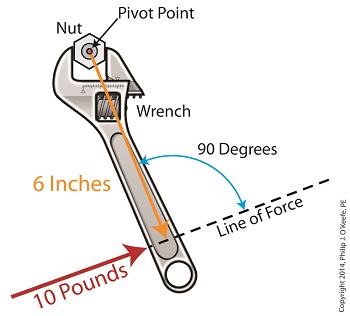
Last time we introduced the mathematical formula for torque, which is most simply defined as a measure of how much a force acting upon an object causes that object to rotate around a pivot point. When manipulated, torque can produce a mechanical advantage in gear trains and tools, which we’ll see later. The formula is: Torque = Distance × Force × sin(ϴ) We learned that the factors Distance and Force are vectors, and sin(ϴ) is a trigonometric function of the angle ϴ which is formed between their two vectors. Let’s return to our wrench example and see how the torque formula works. Vectors have both a magnitude, that is, a size or extent, and a direction, and they are typically represented in physics and engineering problems by straight arrows. In our illustration the vector for distance is represented by an orange arrow, while the vector for force is represented by a red arrow. The orange distance vector has a magnitude of 6 inches, while the red force vector has a magnitude of 10 pounds, which is being supplied by the user’s arm muscle manipulating the nut. That muscle force follows a path from the arm to the pivot point located at the center of the nut, a distance of 6 inches. Vector arrows point in a specific direction, a direction which is indicative of the way in which the vectors’ magnitudes — in our case inches of distance vs. pounds of force — are oriented with respect to one another. In our illustration the orange distance vector points away from the pivot point. This is according to engineering and physics convention, which dictates that, when a force vector is acting upon an object to produce a torque, the distance vector always points from the object’s pivot point to the line of force associated with the force vector. The angle, ϴ, that is formed between the two vectors in our example is 90 degrees, as measured by any common, ordinary protractor. Next we must determine the trigonometric value for sin(ϴ). This is easily accomplished by simply entering “90” into our calculator, then pressing the sin button. An interesting fact is that when the angle ϴ ranges anywhere between 0 and 90 degrees, the values for sin(ϴ) always range between 0 and 1. To see this in action enter any number between 0 and 90 into a scientific calculator, then press the sin button. For our angle of 90 degrees we find that, sin(90) = 1 Thus the formula for torque in our example, because the sin(ϴ) is equal to 1, simply becomes the product of the magnitudes of the Distance and Force vectors: Torque = Distance × Force × sin(90) Torque = Distance × Force × 1 Torque = Distance × Force Next time we’ll insert numerical values into the equation and see how easily torque can be manipulated. _______________________________________ |
How A Power Plant Condenser Works, Part 2
Sunday, October 6th, 2013|
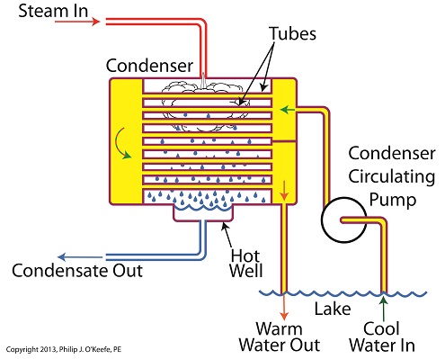
Winter is fast approaching. Imagine living in a house without insulation. Now imagine your heating bill, which will be high due to the tremendous amount of heat loss. Energy is a precious resource, no matter how it’s produced, and its conservation within a power plant’s steam/water cycle is of vital importance. Last time we learned about the transfer of heat energy within a power plant’s condenser, where some of the heat energy contained within its steam is absorbed by the cool lake water contained inside its tubes. Steam is continuously flowing into the condenser from the steam turbine, so it’s essential for the circulating pump to keep a fresh supply of lake water flowing through the condenser’s tubes in an effort to keep temperatures under control. The compensating action that’s provided by the cool lake water flowing within the tubes, represented by green arrows in the illustration, keeps the temperature inside the tubes from rising and becoming equal to the steam’s temperature outside of them. If the flow of cool water through the tubes were to stop and the temperatures inside and outside the tubes become equal, the water contained inside the tubes would boil off to steam, resulting in the tubes bursting and a wrecked condenser. After absorbing heat energy from the surrounding steam, the warmed lake water within the tubes follows a circuitous path through the tubing, eventually emptying out into the lake. The orange arrows in the illustration show this path. Okay, with this warm water entering the lake, doesn’t that harm the eco system? Actually its impact is negligible. You see, the temperature of the lake water leaving the condenser is only about 10°F higher than when it was pumped from the lake. Add this to the fact that the volume of water contained within a lake is huge in comparison to the small amount of warmed water being returned to it. Next week we’ll see how the loss of heat energy affects the steam, and how an important part of the condenser known as the hot well comes into play. ________________________________________ |
How A Power Plant Condenser Works, Part 1
Wednesday, October 2nd, 2013|
Last time we began our discussion on power plant inefficiencies and indentified a major contributor, the heat energy dispelled into the atmosphere through the turbine exhaust. Today we’ll see how a piece of equipment known as the condenser comes into play to deal with this problem. Let’s see how it works. First, water from our plant’s water source, say a nearby lake, is siphoned into the condenser circulating pump, which delivers it to the condenser. This lake water path appears in yellow. You’ll notice that the lake water follows a circuitous path from the lake, through the condenser circulating pump, then the condenser tubes, until finally it is returned to the lake. Now the cool lake water, denoted by green arrows, is made to pass through the condenser’s many tubes, while steam from the turbine exhaust surrounds them. The tubes keep the lake water segregated from the cloud of steam surrounding them inside the condenser vessel. In other words, the lake water’s path is a closed system, never coming into direct physical contact with the surrounding steam. What’s happening inside our condenser is demonstrative of a fundamental principle of thermal engineering, that is, that hot will travel in the direction of cold. More specifically, within our condenser the heat energy in the steam cloud surrounding the condenser tubes will be attracted to the cool lake water contained within the tubes. This causes the heat energy contained within the steam to leave it, and get absorbed by the cool lake water flowing within the tubes. We’ll begin to find out how these dynamics influence what’s happening with our water-to-steam power plant cycle next time.
________________________________________ |


