Posts Tagged ‘engineer’

Tangential Velocity

Monday, August 14th, 2017

   Last time we introduced the Mechanical Power Formula, which is used to compute power in pulley-belt assemblies, and we got as far as introducing the term tangential velocity, V, a key variable within the Formula.   Today we’ll devise a new formula to compute this tangential velocity.

   Our starting point is the formula introduced last week to compute the amount of power, P, in our pulley-belt example is, again,

P = (T1 – T2) × V                                         (1)

   We already know that P is equal to 4 horsepower, we have yet to determine the belt’s tight side tension, T1, and loose side tension, T2, and of course V, the formula for which we’ll develop today.


Tangential Velocity

Tangential Velocity


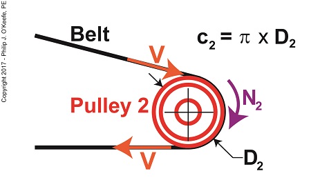
   Tangential velocity is dependent on both the circumference, c2, and rotational speed, N2, of Pulley 2.  The circumference represents the length of Pulley 2’s curved surface.   The belt travels part of this distance as it makes its way from Pulley 2 back to Pulley 1. The rotational speed, N2, represents the rate that it takes for Pulley 2’s curved surface to make one revolution while propelling the belt.   This time period is known as the period of revolution, t2, and is related to N2 by this equation,

N2 = 1 ÷ t2                                                                         (2)

   The rotational speed of Pulley 2 is specified in our example as 300 RPMs, or revolutions per minute, and we’ll denote that speed as N2 in light of the fact it’s referring to speed present at the location of Pulley 2.   As we build the formula, we’ll be converting N2 into velocity, specifically tangential velocity, V, which is the velocity at which the belt operates, this in turn will enable us to solve equation (1).

   Why speak in terms of tangential velocity rather than plain old ordinary velocity?  Because the moving belt’s orientation to the surface of the pulley lies at a tangent in relation to the pulley’s circumference, c2, as shown in the above illustration.   Put another way, the belt enters and leaves the curved surface of the pulley in a straight line.

   Generally speaking, velocity is distance traveled over a period of time, and tangential velocity is no different.  So taking time into account we arrive at this formula,

V = c2 ÷ t2                                                                          (3)

   Since the surface of Pulley 2 is a circle, its circumference can be computed using a formula developed thousands of years ago by the Greek engineer and mathematician Archimedes.   It is,

c2 = π × D2                                                            (4)

where D2 is the diameter of the pulley and π represents the constant 3.1416.

   We now arrive at the formula for tangential velocity by combining equations (3) and (4),

V = π × D2 ÷ t2                                                    (5)

   Next time we’ll plug numbers into equation (5) and solve for V.

Copyright 2017 – Philip J. O’Keefe, PE

Engineering Expert Witness Blog

____________________________________


What Belt Width does a Hydroponics Plant Need?

Friday, June 23rd, 2017

    Belts are important.  They make fashion statements, hold things up, keep things together.   Today we’re introducing a scenario in which the Euler-Eytelwein Formula will be used to, among other things, determine the ideal width of a belt to be used in a mechanical power transmission system consisting of two pulleys inside a hydroponics plant.   The ideal width belt would serve to maximize friction between the belt and pulleys, thus controlling slippage and maximizing belt strength to prevent belt breakage.

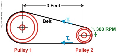
    An engineer is tasked with designing an irrigation system for a hydroponics plant.   Pulley 1 is connected to the shaft of a water pump, while Pulley 2 is connected to the shaft of a small gasoline engine.

What Belt Width does a Hydroponics Plant Need?

What Belt Width does a Hydroponics Plant Need?

    Mechanical power is transmitted by the belt from the engine to the pump at a constant rate of 4 horsepower.   The belt material is leather, and the two pulleys are made of cast iron.   The coefficient of friction, μ, between these two materials is 0.3, according  to Marks Standard Handbook for Mechanical Engineers.   The belt manufacturer specifies a safe working tension of 300 pounds force per inch width of the belt.   This is the maximum tension the belt can safely withstand before breaking.

    We’ll use this information to solve for the ideal belt width to be used in our hydroponics application.    But first we’re going to have to re-visit the two T’s of the Euler-Eytelwein Formula.   We’ll do that next time.


Copyright 2017 – Philip J. O’Keefe, PE

Engineering Expert Witness Blog

____________________________________


Mechanical Overkill, an Undesirable Tradeoff in Compound Pulleys

Wednesday, November 30th, 2016

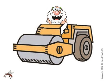
    We’ve been discussing the mechanical advantage that compound pulleys provide to humans during lifting operations and last time we hit upon the fact that there comes a point of diminished return, a reality that engineers must negotiate in their mechanical designs.   Today we’ll discuss one of the undesirable tradeoffs that results in a diminished return within a compound pulley arrangement when we compute the length of rope the Grecian man we’ve been following must grapple in order to lift his urn.   What we’ll discover is a situation of mechanical overkill – like using a steamroller to squash a bug.


Mechanical Overkill

Mechanical Overkill


    Just how much rope does Mr. Toga need to extract from our working example compound pulley to lift his urn two feet above the ground?   To find out we’ll need to revisit the fact that the compound pulley is a work input-output device.

    As presented in a past blog, the equations for work input, WI, and work output, WO, we’ll be using are,

WI = F × d2

WO = W × d1

    Now, ideally, in a compound pulley no friction exists in the wheels to impede the rope’s movement, and that will be our scenario today.  Our next blog will deal with the more complex situation where friction is present.   So for our example today, with no friction present, work input equals output…

WI = WO

… and this fact allows us to develop an equation in terms of the rope length/distance factors in our compound pulley assembly, represented by d1 and d2, …

F × d2 = W × d1

d2 ÷ d1 = W ÷ F

    Now, from our last blog we know that W divided by F represents the mechanical advantage, MA, to Mr. Toga of using the compound pulley, which was found to be 16, equivalent to the sections of rope directly supporting the urn.   We’ll set the distance factors up in relation to MA, and the equation becomes…

d2 ÷ d1 = MA

d2 = MA ×  d1

d2 = 16 × 2 feet = 32 feet

    What we discover is that in order to raise the urn 2 feet, our Grecian friend must manipulate 32 feet of rope – which would only make sense if he were lifting something far heavier than a 40 pound urn.

    In reality, WI does not equal WO, due to the inevitable presence of friction.   Next time we’ll see how friction affects the mechanical advantage in our compound pulley.

 Copyright 2016 – Philip J. O’Keefe, PE

Engineering Expert Witness Blog

____________________________________


Forms of Heat Energy – Latent

Monday, July 15th, 2013

      If you took high school chemistry, you learned that water is created when two gases, hydrogen and oxygen are combined.   You may have even been lucky enough to have a teacher who was able to perform this magical transformation live during class.

      Depending primarily on the amount of heat energy absorbed, water exists in one of the three states of matter, gas, liquid, or solid.   Its states also depend on surrounding atmospheric pressure, but more about that later.    For our discussion, the water will reside at the atmospheric pressure present at sea level, which is around 14.7 pounds per square inch.

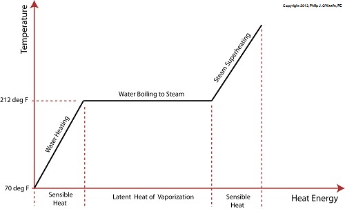
      Last time we learned that the heat energy absorbed by water before it begins to boil inside our example tea kettle is known as sensible heat within the field of thermodynamics.   The more sensible heat that’s applied, the more the water temperature rises, but only up to a point.

      The boiling point of water is 212°F.    In fact this is the maximum temperature it will achieve, no matter how much heat energy is applied to it.   That’s because once this temperature is reached water begins to change its state of matter so that it becomes steam.   At this point the energy absorbed by the water is said to become the latent heat of vaporization, that is, the energy absorbed by the water becomes latent, or masked to the naked eye, because it is working behind the scenes to transform the water into steam.

      As the water in a tea kettle is transformed into steam, it expands and escapes through the spout, producing that familiar shrill whistle.   But what if we prevented the steam from dispersing into the environment and continued to add heat energy?   Ironically enough, under these conditions temperature would continue to rise, upwards of 1500°F, if the stove’s burner were powerful enough.   This process is known as superheating.   Now hold your hats on, because even more ironically, the heat added to this superheated steam is also said to be sensible heat.

      Confused?    Let’s take a look at the graph below to clear things up.

power plant engineering

      Sensible heat is heat energy that’s added to water, H2O, in its liquid state.   It’s also the term used to describe the heat energy added to steam that’s held within a captive environment, such as takes place during superheating.    On the other hand, the latent heat of vaporization, that is the heat energy that’s applied to water once it’s reached boiling point, does not lead to a further rise in temperature, as least as measured by a thermometer.

      Next time we’ll see how surrounding air pressure affects water’s transition from liquid to steam.

___________________________________________