Last time we learned how pneumatic actuators impart linear motion to machines. Now, let’s see how the pneumatic actuator is connected to the depositor’s pump. The connection imparts linear motion to the pump so it draws in jelly filling from the supply hopper and sends it streaming out of the nozzle onto a passing pastry.
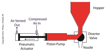
On the depositor, the pneumatic actuator’s piston rod is connected to the pump’s piston. As such, the pistons in the actuator and pump move together. When compressed air is admitted to the right side of the pneumatic actuator, the pistons in actuator and pump move to the left. As the pump’s piston moves to the left, a vacuum is formed in the pump. This vacuum sucks the jelly out of the hopper, through the diverter valve, and into the pump as shown below.
The Depositor’s Pneumatically Actuated Pump
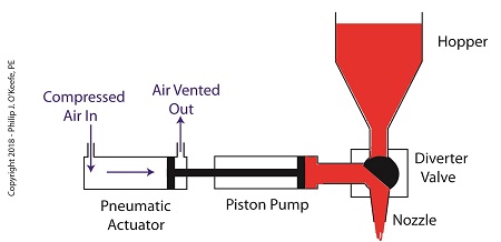
Once the pump is full of jelly, compressed air is admitted to the left side of the actuator piston. The pistons in actuator and pump move to the right as the compressed air expands and presses against the piston in the actuator. As the pump’s piston moves to the right, pressure builds up on the jelly in the pump. The pressure empties the jelly from the pump. The jelly is forced from the pump, back through the diverter valve, and it streams out of the nozzle as shown below.
The Depositor’s Pneumatic Actuator Empties the Pump
For the pumping process to take place, the diverter valve must be rotated to first allow jelly to flow from the hopper. The diverter valve must be rotated again to allow jelly to flow through the nozzle. Next time, we’ll see how a pneumatic actuator is attached to a mechanical linkage that rotates the diverter valve.
Last time we learned that a fruit jelly depositor in a food manufacturing plant is an example of a positive displacement pump at work. Today we’ll see how pieces of equipment on the depositor, known as a pneumatic actuators, work. Pneumatic actuators do not come in contact with the jelly flowing through the depositor. In other words, no jelly flows through the actuators. The jelly only flows through the transfer valve and positive displacement pump as we saw last time. The pump and valve can’t move by themselves. So, they need some device to set them in motion. That’s where the pneumatic actuators come into play. They impart movement to the pump and transfer valve to get the jelly flowing from the hopper and down through the nozzle and onto the pastry.
A pneumatic actuator is a device that operates using compressed air. Compressed air, from an external air compressor, enters into a tube in the actuator known as a cylinder. Inside the cylinder is a piston that can move along the length of the tube. Attached to the piston is a piston rod which extends to the outside of the cylinder.
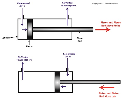
When compressed air is introduced into the cylinder on the left side of the piston, it forces the piston and piston rod to move towards the right side of the cylinder. But, air must be vented out to atmosphere from the right side of the piston for this movement to occur. If no venting took place, trapped air to the right of the piston will get squeezed between the piston and the right end of the cylinder. When the air gets squeezed, it becomes pressurized. The pressure will impede the movement of the piston.
Likewise, when compressed air is introduced into the cylinder on the right side of the piston, it forces the piston and piston rod to move towards the left side of the cylinder.
The Depositor’s Pneumatic Actuator
So, depending on which end compressed air is admitted to the pneumatic actuator’s cylinder, the piston rod will move to the left or the right. In engineering terms, the actuator imparts linear motion to machines. In other words, the piston rod moves back and forth in a straight line.
Next time, we’ll see how the pneumatic actuator is connected to the depositor’s pump to impart the linear motion that draws jelly from the supply hopper and sends it streaming out of the nozzle onto a passing pastry.
Last time we learned that the human heart functions as the greatest of all positive displacement pumps, moving a set quantity of blood through it at precise intervals during its operating cycle. Today we’ll begin our exploration into how positive displacement pumps are used in industry, specifically within a food manufacturing plant.
At one point in my career I was employed as a design engineer in a food manufacturing plant. The plant was owned by the leading manufacturer of bakery products in the United States, responsible for supplying restaurants, bakeries, and grocery stores with finished and partially finished pastry goods that they would then resell. The plant produced vast amounts of puff pastry dough products, all of which were formed and filled with various fillings while zipping along on a production line conveyor belt. One of the products was a fruit filled pastry in which the belt moved so quickly, depositing fruit fillings into the dough by hand would be impossible, resulting in a frenzied mess similar to what Lucy encountered when she worked in a candy factory.
Clearly, an automated machine would work better in this and other scenarios. We’ll see how one known as a depositor functions on a food pastry line next time.
Last time we performed an engineering experiment that demonstrated how we can lower the boiling point of water inside a lidded pot without applying heat if we use a vacuum pump to lower the pot’s internal pressure. We discovered that when pressure was lowered to 0.25 pounds per square inch (PSI), the water inside the pot turned to steam at a mere 59ºF, which initiated the cavitationprocess. Today we’ll see how centrifugal pumpscan also create vacuums to initiate cavitation.
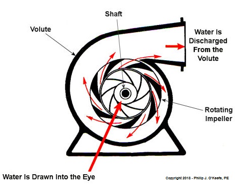
Centrifugal Pumps Can Create Vacuums
As we learned in a past blog, centrifugal pumps contain rotating impellers within a housing called a volute. This housing has an inlet, known as an eye, where water flows into the pump from a pipe, and an outlet, known as a discharge, where water flows out of the pump. The centrifugal pump creates a vacuum by mimicking the action of sucking soda through a straw. The spinning impeller draws water into the housing by creating low pressure at the inlet, and if the pressure gets low enough, we’ll recreate what happened in our vacuum pump and pot experiment. Water will boil at temps far lower than normal boiling point of 212 ºF. Just as in our experiment, if pressure is lowered to 0.23 PSI, water present at the pump inlet will boil at 59ºF, causing thousands of tiny steam bubbles to form and the pump to cavitate.
They’re just tiny bubbles, so what harm can they do? We’ll find out next time.
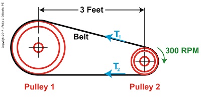
Belts are important. They make fashion statements, hold things up, keep things together. Today we’re introducing a scenario in which the Euler-Eytelwein Formulawill be used to, among other things, determine the ideal width of a belt to be used in a mechanical power transmission system consisting of two pulleys inside a hydroponics plant. The ideal width belt would serve to maximize friction between the belt and pulleys, thus controlling slippage and maximizing belt strength to prevent belt breakage.
An engineer is tasked with designing an irrigation system for a hydroponics plant. Pulley 1 is connected to the shaft of a water pump, while Pulley 2 is connected to the shaft of a small gasoline engine.
What Belt Width does a Hydroponics Plant Need?
Mechanical power is transmitted by the belt from the engine to the pump at a constant rate of 4 horsepower. The belt material is leather, and the two pulleys are made of cast iron. The coefficient of friction, μ, between these two materials is 0.3, according to Marks Standard Handbook for Mechanical Engineers. The belt manufacturer specifies a safe working tension of 300 pounds force per inch width of the belt. This is the maximum tension the belt can safely withstand before breaking.
We’ll use this information to solve for the ideal belt width to be used in our hydroponics application. But first we’re going to have to re-visit the two T’s of the Euler-Eytelwein Formula. We’ll do that next time.
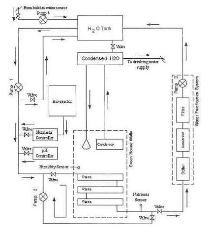
Last week we saw how friction coefficientsas used in the Euler-Eyelewein Formula, can be highly specific to a specialized application, U.S. Navy ship capstans. In fact, many diverse industries benefit from aspects of the Euler-Eytelwein Formula. Today we’ll introduce anotherengineeringapplicationof theFormula, exploring its use within the irrigation system of a hydroponics plant.
Another Specialized Application of the Euler-Eyelewein Formula
Pumps conveying water are an indispensable part of a hydroponics plant. In the schematic shown here they are portrayed by the symbol ⊗.
In our simplified scenario to be presented next week, these pumps are powered by a mechanical power transmission system, each consisting of two pulleys and a belt. One pulley is connected to a water pump, the other pulley to a gasoline engine. A belts runs between the pulleys to deliver mechanical power from the engine to the pump.
The width of the belts is a key component in an efficiently running hydroponics plant. We’ll see how and why that’s so next time.
Last time we began our discussion on Preproduction, the final aspect of the Development stage of our systems engineering approach to medical device design. This is the point at which a small amount of devices are put into actual production, then evaluated for full production possibility. It is also the final juncture at which problems will be evaluated and corrected before full commercial production can begin.
Once the medical devices produced during Preproduction are assembled, they’re subjected to rigorous testing in both a laboratory and the field. This testing is necessary to see if stakeholder requirements are satisfied. At this stage devices constructed en masse on the factory assembly line are compared to prototypes built by hand by design engineers earlier in the Development stage.
During Preproduction laboratory test data is gathered and analyzed by engineers to assess how the device will hold up during actual use. Real-life conditions are simulated in the lab environment to facilitate this process. For example, lab testing of a Preproduction kidney dialysis machine can determine whether its blood pump flow rate falls within acceptable range during hundreds of hours of operation. Other factors, such as durability of materials are evaluated during lab testing. In the case of the dialysis machine, there is a component called a dialyzer that filters toxic waste from blood. Over the duration of the lab test, the material used in the dialyzer filter membranes would be inspected and evaluated for durability.
Next week we’ll conclude our discussion on Preproduction to see what happens when testing is moved outside the lab environment into the field.
Electric motors are everywhere, from driving the conveyor belts, tools, and machines found in factories, to putting our household appliances in motion. The first electric motors appeared in the 1820s. They were little more than lab experiments and curiosities then, as their useful potential had not yet been discovered. The first commercially successful electric motors didn’t appear until the early 1870s, and they could be found driving industrial devices such as pumps, blowers, and conveyor belts.
In our last blog we learned how a latched electric relay was unlatched at the push of a button, using red and green light bulbs to illustrate the control circuit. Now let’s see in Figure 1 how that circuit can be modified to include the control of an electric motor that drives, say, a conveyor belt inside a factory.
Figure 1
Again, red lines in the diagram indicate parts of the circuit where electrical current is flowing. The relay is in its normal state, as discussed in a previous article, so the N.O. contacts are open and the N.C. contact is closed. No electric current can flow through the conveyor motor in this state, so it isn’t operating. Our green indicator bulb also does not operate because it is part of this circuit. However current does flow through the red indicator bulb via the closed N.C. contact, causing the red bulb to light.
The red and green bulbs are particularly useful as indicators of the action taking place in the electric relay circuit. They’re located in the conveyor control panel along with Buttons 1 and 2, and together they keep the conveyor belt operator informed as to what’s taking place on the line, such as, is the belt running or stopped? When the red bulb is lit the operator can tell at a glance that the conveyor is stopped. When the green bulb is lit the conveyor is running.
So why not just take a look at the belt itself to see what’s happening? Sometimes that just isn’t possible. Control panels are often located in central control rooms within large factories, which makes it more efficient for operators to monitor and control all operating equipment from one place. When this is the case, the bulbs act as beacons of the activity taking place on the line. Now, let’s go to Figure 2 to see what happens when Button 1 is pushed.
Figure 2
The relay’s wire coil becomes energized, causing the relay armatures to move. The N.C. contact opens and the N.O. contacts close, making the red indicator bulb go dark, the green indicator bulb to light, and the conveyor belt motor to start. With these conditions in place the conveyor belt starts up.
Now, let’s look at Figure 3 to see what happens when we release Button 1.
Figure 3
With Button 1 released the relay is said to be “latched” because current will continue to flow through the wire coil via one of the closed N.O. contacts. In this condition the red bulb remains unlit, the green bulb lit, and the conveyor motor continues to run without further human interaction. Now, let’s go to Figure 4 to see how we can stop the motor.
Figure 4
When Button 2 is depressed current flow through the relay coil interrupted. The relay is said to be unlatched and it returns to its normal state where both N.O. contacts are open. With these conditions in place the conveyor motor stops, and the green indicator bulb goes dark, while the N.C. contact closes and the red indicator bulb lights. Since the relay is unlatched and current no longer flows through its wire coil, the motor remains stopped even after releasing Button 2. At this point we have a return to the conditions first presented in Figure 1. The ladder diagram shown in Figure 5 represents this circuit.
Figure 5
Next time we’ll introduce safety elements to our circuit by introducing emergency buttons and motor overload switches.
Pumps are all around us. They keep our drinking water flowing, the cooling water circulating in your car’s engine, and even your blood flowing. They’re essential in many aspects of our lives, but most of us don’t think too much about them. For our discussion let’s put them into two categories: positive displacement pumps and centrifugal pumps. This week, we’ll focus on positive displacement pumps.
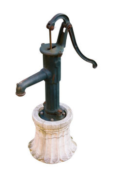
Positive displacement pumps, as their name implies, displace a quantity of liquid with each complete cycle of movement. This takes place when moving parts of the pump take “bites” out of the liquid at the inlet, then force them to exit through the outlet. A familiar example of a positive displacement pump is the type of hand operated water pump that’s commonly found in campgrounds. See Figure 1.
Figure 1 – A Positive Displacement Pump
This type of pump is known as a reciprocating positive displacement pump. By reciprocating, I mean that the moving parts travel back and forth in a straight line during its operation. Let’s see how it works by referring to the cutaway view in Figure 2.
Figure 2 – Cutaway View of the Pump Shown in Figure 1
In the cutaway view, the pump’s piston and internal check valve are shown, and there’s another check valve in the bottom of the pump housing. When you pull up on the handle, the piston moves down into the water in the pump housing, and the pressure caused by this movement forces the check valve in the bottom to slam closed, while the check valve above is forced open. This causes water movement to flood through the open check valve and fill up the space above the piston. When you push down on the handle, the opposite happens. The piston is made to move upward. The upward acceleration of the water above the piston causes the check valve on the piston to slam shut, and this traps the water above it. As the piston moves back up, a suction is created below, which causes the check valve in the bottom of the housing to pop open and more water is drawn up into the space below the piston. Eventually, when the piston gets high enough, the water trapped on top of it will flow out of the spigot.
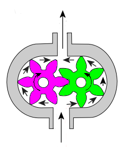
Another type of positive displacement pump is represented by a rotary pump. These pumps operate in a circular motion to move a volume of liquid with each revolution of the pump shaft. This is done by trapping liquid between moving parts, such as gears, lobes, vanes, or screws, and the stationary pump housing itself.
To show how this works, refer to the gear pump shown in Figure 3. Its gear teeth mesh together in the middle of the pump, blocking the flow from going straight through and trapping it within the spaces formed by rotating gear teeth and the pump housing. It’s like the water is being forced through a turnstile.
Figure 3 – A Cutaway View of a Gear Pump
Next week, we’ll talk about centrifugal pumps and how they move liquids along using centrifugal force.
Last time we talked about some general concepts in an area of mechanical engineering known as thermodynamics. In this week’s article we’ll narrow our focus a bit to look at a part of thermodynamics that deals with power cycles.
One mammoth example of a power cycle can be found in a coal-fired power plant. You can’t help but notice these plants with their massive buildings, mountains of coal, and tall smoke stacks. They’ve been getting a lot of negative press lately and are a central focus of the debate on global warming, but most people have no idea what’s going on inside of them. Let’s take a peek.
Figure 1 – A Coal-Fired Power Plant
A power plant has one basic function, to convert the chemical energy in coal into the electrical energy that we use in our modern lives, and it’s a power cycle that is at the heart of this conversion process. The most basic power cycle in this instance would include a boiler, steam turbine, condenser, and a pump (see Figure 2 below).
Figure 2 – A Basic Power Cycle
When the coal is burned in the power plant furnace, its chemical energy is turned into heat energy. This heat energy and the boiler are enclosed by the furnace so the boiler can more efficiently absorb the heat energy to make steam. A pipe carries the steam from the boiler to a steam turbine. Nozzles in the steam turbine convert the heat energy of the steam into kinetic energy, making the steam pick up speed as it leaves the nozzles. The fast moving steam transfers its kinetic energy to the turbine blades, causing the turbine to spin, much like a windmill (see Figure 3 below).
Figure 3 – The Inner Workings of a Steam Turbine
The spinning turbine is connected by a shaft to a generator. The turbine works to spin the generator and thus produces electricity. After the energy in the steam is used by the turbine, it goes to the condenser, whose job it is to convert the steam back into water. To accomplish this, the condenser uses cold water, say from a nearby lake or river, to cool the steam down until it converts from a gas back to a liquid, that is, water. This is why power plants are normally found adjacent to a body of water. After things are cooled down, the pump gets to work, pushing the condensed water back into the boiler where it is once again turned into steam. This power cycle keeps repeating itself as long as there is coal being burned in the furnace, the plant equipment is functioning properly, and electrical energy flows out of the power plant.
Thermodynamics sets up an energy accounting system that enables mechanical engineers to design and analyze power cycles to make sure they are safe, reliable, efficient, and economical. When all is said and done, a properly designed power cycle transfers as much heat energy as possible from the burning coal on one end of the cycle to meet the requirements for electrical power on the other end of the cycle. As was mentioned in last week’s blog, nothing is 100% efficient.
Next time we’ll learn about being cool. No, I’m not going to talk about the latest cell phone gadget or who’s connected on Facebook. We’ll be covering refrigeration cycles.


