Posts Tagged ‘piston rod’
Monday, July 9th, 2018
|
Last time, we learned how a pneumatic actuator was connected to a depositor’s positive displacement piston pump so that it could extract jelly filling from a hopper, and deposit it through a nozzle onto a passing pastry. The pneumatic actuator imparted linear motion to the pump during this process. Since the pistons in the actuator and pump both move in a straight line, it was very easy and straightforward to connect the actuator to the pump.
For the depositing process to work, we must have an additional actuator to rotate the diverter valve as the pump operates. The valve changes the flow path of the jelly between the hopper and the nozzle. More specifically, the valve must rotate clockwise to create a flow path between the hopper and the pump while the pump extracts jelly from the hopper.
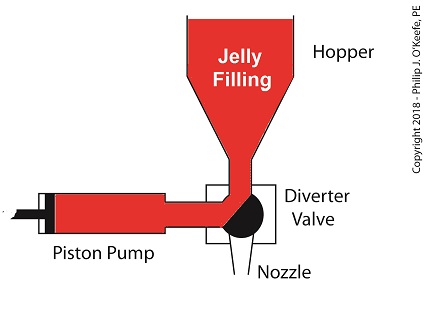
The Diverter Valve Rotated Clockwise
When the pump is full of jelly, the diverter valve must rotate counter-clockwise to create a flow path between the pump and the nozzle. This path allows the pump to empty its contents trough the nozzle.
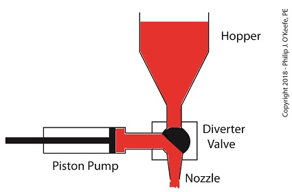
The Diverter Valve Rotated Counter-Clockwise
Although the diverter valve’s motion is rotary, it can be operated with the linear motion of a pneumatic actuator. To convert the linear motion of the actuator to the rotary motion needed to operate the valve, we can employ a device known to engineers as a Scotch Yoke.
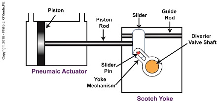
The Depositor’s Scotch Yoke
In the Scotch Yoke, the pneumatic actuator’s piston rod is connected to a slider. As the piston moves back and forth in the pneumatic actuator, the slider is free to move back and forth along a fixed guide rod. A pin is located on the slider. The pin loosely engages a slot in the yoke mechanism. As the slider moves, the pin can move freely in the slot. The yoke mechanism is rigidly attached to the rotating diverter valve shaft.
Next time, we’ll look at the rotary motion of the Scotch Yoke as the pneumatic actuator piston moves to the right and then to the left during the jelly depositing process.
Copyright 2018 – Philip J. O’Keefe, PE
Engineering Expert Witness Blog
____________________________________ |
Tags: depositor, diverter valve, engineering, guide rod, hopper, jelly filling, linear motion, nozzle, piston, piston rod, pneumatic actuator, positive displacement pump, rotary motion, Scotch Yoke, slider, yoke mechanism
Posted in Engineering and Science, Expert Witness, Forensic Engineering, Innovation and Intellectual Property, Personal Injury, Product Liability | Comments Off on The Depositor’s Scotch Yoke
Monday, July 2nd, 2018
|
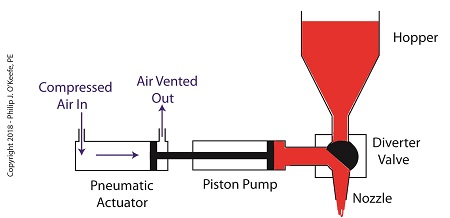
Last time we learned how pneumatic actuators impart linear motion to machines. Now, let’s see how the pneumatic actuator is connected to the depositor’s pump. The connection imparts linear motion to the pump so it draws in jelly filling from the supply hopper and sends it streaming out of the nozzle onto a passing pastry.
On the depositor, the pneumatic actuator’s piston rod is connected to the pump’s piston. As such, the pistons in the actuator and pump move together. When compressed air is admitted to the right side of the pneumatic actuator, the pistons in actuator and pump move to the left. As the pump’s piston moves to the left, a vacuum is formed in the pump. This vacuum sucks the jelly out of the hopper, through the diverter valve, and into the pump as shown below.
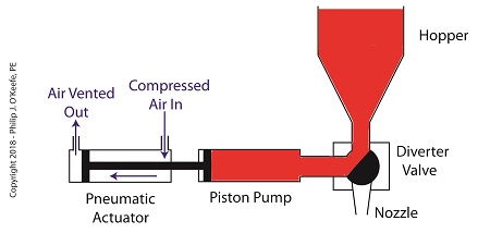
The Depositor’s Pneumatically Actuated Pump
Once the pump is full of jelly, compressed air is admitted to the left side of the actuator piston. The pistons in actuator and pump move to the right as the compressed air expands and presses against the piston in the actuator. As the pump’s piston moves to the right, pressure builds up on the jelly in the pump. The pressure empties the jelly from the pump. The jelly is forced from the pump, back through the diverter valve, and it streams out of the nozzle as shown below.
The Depositor’s Pneumatic Actuator Empties the Pump
For the pumping process to take place, the diverter valve must be rotated to first allow jelly to flow from the hopper. The diverter valve must be rotated again to allow jelly to flow through the nozzle. Next time, we’ll see how a pneumatic actuator is attached to a mechanical linkage that rotates the diverter valve.
Copyright 2018 – Philip J. O’Keefe, PE
Engineering Expert Witness Blog
____________________________________ |
Tags: compressed air, depositor, jelly filling, linear motion, pastry, piston, piston rod, pneumatic actuator, pump, pump vacuum
Posted in Engineering and Science, Expert Witness, Forensic Engineering, Innovation and Intellectual Property, Personal Injury, Product Liability | Comments Off on The Depositor’s Pneumatically Actuated Pump
Thursday, June 21st, 2018
|
Last time we learned that a fruit jelly depositor in a food manufacturing plant is an example of a positive displacement pump at work. Today we’ll see how pieces of equipment on the depositor, known as a pneumatic actuators, work. Pneumatic actuators do not come in contact with the jelly flowing through the depositor. In other words, no jelly flows through the actuators. The jelly only flows through the transfer valve and positive displacement pump as we saw last time. The pump and valve can’t move by themselves. So, they need some device to set them in motion. That’s where the pneumatic actuators come into play. They impart movement to the pump and transfer valve to get the jelly flowing from the hopper and down through the nozzle and onto the pastry.
A pneumatic actuator is a device that operates using compressed air. Compressed air, from an external air compressor, enters into a tube in the actuator known as a cylinder. Inside the cylinder is a piston that can move along the length of the tube. Attached to the piston is a piston rod which extends to the outside of the cylinder.
When compressed air is introduced into the cylinder on the left side of the piston, it forces the piston and piston rod to move towards the right side of the cylinder. But, air must be vented out to atmosphere from the right side of the piston for this movement to occur. If no venting took place, trapped air to the right of the piston will get squeezed between the piston and the right end of the cylinder. When the air gets squeezed, it becomes pressurized. The pressure will impede the movement of the piston.
Likewise, when compressed air is introduced into the cylinder on the right side of the piston, it forces the piston and piston rod to move towards the left side of the cylinder.
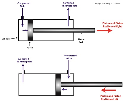
The Depositor’s Pneumatic Actuator
So, depending on which end compressed air is admitted to the pneumatic actuator’s cylinder, the piston rod will move to the left or the right. In engineering terms, the actuator imparts linear motion to machines. In other words, the piston rod moves back and forth in a straight line.
Next time, we’ll see how the pneumatic actuator is connected to the depositor’s pump to impart the linear motion that draws jelly from the supply hopper and sends it streaming out of the nozzle onto a passing pastry.
Copyright 2018 – Philip J. O’Keefe, PE
Engineering Expert Witness Blog
____________________________________ |
Tags: compressed air, compressor, cylinder, depostitor, engineering, food manufacturing, linear motion, piston, piston rod, pneumatic actuator, pump, transfer valve
Posted in Engineering and Science, Expert Witness, Forensic Engineering, Innovation and Intellectual Property, Personal Injury, Product Liability | Comments Off on The Depositor’s Pneumatic Actuator
Wednesday, December 6th, 2017
|
Last time we developed an engineering formula to calculate the horsepower required to accelerate a flywheel by way of a reciprocating steam engine, which contributes to the storage of kinetic energy inside a flywheel. Today we’ll gain a clearer understanding of how this works when we take a look inside a reciprocating steam engine.
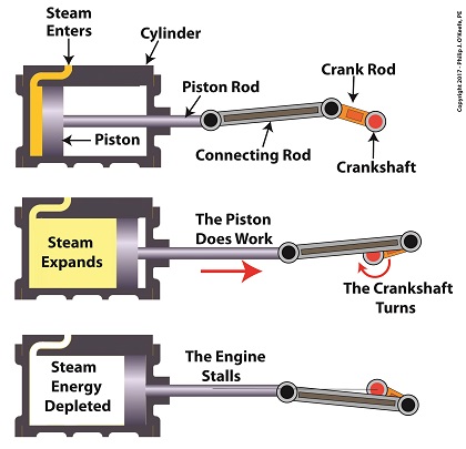
A Look Inside a Reciprocating Steam Engine
A reciprocating steam engine performs the work of transforming steam’s heat energy into the mechanical energy needed to move a piston contained within a cylinder. During a complete operating cycle this piston travels from one end of the cylinder to the other, then back again. This is made possible because during the first half of the cycle pressurized steam enters one end of the cylinder and expands inside it, forcing the piston to move.
This process inside the cylinder results in movement of a piston that’s attached to a piston rod, which in turn is connected to a crankshaft via a connecting rod and crank rod. The crankshaft is a device which converts the reciprocating linear motion of an engine’s piston into rotary motion and in so doing facilitates the powering of any externally mounted rotating machinery attached to it. So long as there’s ample steam to power the internal piston, over time, energy in the form of horsepower will be available to externally mounted devices. The energy in the steam decreases as the steam expands behind the moving piston. So, the engine’s horsepower, will decrease as the piston travels to the end of the cylinder. If the energy in the steam should become depleted, the reciprocating steam engine will stall. The engine will no longer be able to perform work.
Next time we’ll see how a crankshaft works when we take a look inside it.
opyright 2017 – Philip J. O’Keefe, PE
Engineering Expert Witness Blog
____________________________________ |
Tags: connecting rod, crank rod, crankshaft, energy, engineering, flywheel, kinetic energy, piston rod, power, reciprocating steam engine, work
Posted in Engineering and Science, Expert Witness, Forensic Engineering, Innovation and Intellectual Property, Personal Injury, Product Liability | Comments Off on A Look Inside a Reciprocating Steam Engine


