Posts Tagged ‘nozzle’

The Depositor’s Scotch Yoke

Monday, July 9th, 2018

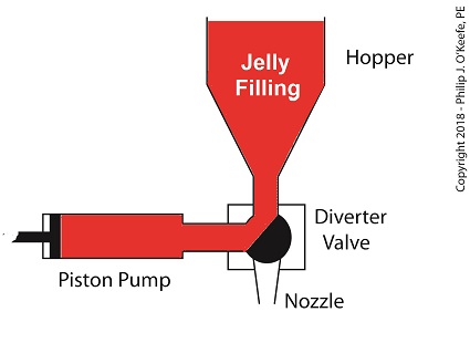
    Last time, we learned how a pneumatic actuator was connected to a depositor’s positive displacement piston pump so that it could extract jelly filling from a hopper, and deposit it through a nozzle onto a passing pastry.   The pneumatic actuator imparted linear motion to the pump during this process.   Since the pistons in the actuator and pump both move in a straight line, it was very easy and straightforward to connect the actuator to the pump.

    For the depositing process to work, we must have an additional actuator to rotate the diverter valve as the pump operates.   The valve changes the flow path of the jelly between the hopper and the nozzle.   More specifically, the valve must rotate clockwise to create a flow path between the hopper and the pump while the pump extracts jelly from the hopper.

The Diverter Valve Rotated Clockwise

The Diverter Valve Rotated Clockwise


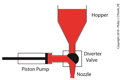
    When the pump is full of jelly, the diverter valve must rotate counter-clockwise to create a flow path between the pump and the nozzle.   This path allows the pump to empty its contents trough the nozzle.

The Diverter Valve Rotated Counter-Clockwise

The Diverter Valve Rotated Counter-Clockwise


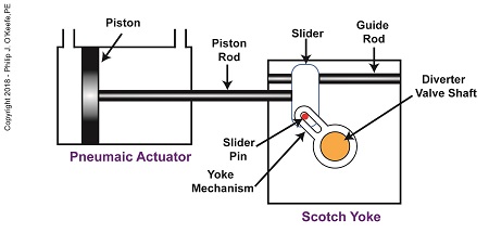
    Although the diverter valve’s motion is rotary, it can be operated with the linear motion of a pneumatic actuator.   To convert the linear motion of the actuator to the rotary motion needed to operate the valve, we can employ a device known to engineers as a Scotch Yoke.

The Depositor’s Scotch Yoke

The Depositor’s Scotch Yoke


    In the Scotch Yoke, the pneumatic actuator’s piston rod is connected to a slider.   As the piston moves back and forth in the pneumatic actuator, the slider is free to move back and forth along a fixed guide rod.   A pin is located on the slider.   The pin loosely engages a slot in the yoke mechanism.   As the slider moves, the pin can move freely in the slot.   The yoke mechanism is rigidly attached to the rotating diverter valve shaft.

    Next time, we’ll look at the rotary motion of the Scotch Yoke as the pneumatic actuator piston moves to the right and then to the left during the jelly depositing process.

Copyright 2018 – Philip J. O’Keefe, PE

Engineering Expert Witness Blog

____________________________________


Food Manufacturing Challenges – Cleanliness

Monday, October 3rd, 2011
     My wife and I have an agreement concerning the kitchen.  She cooks, I clean.  Plates and utensils are easy enough to deal with, especially when you have a dishwasher.  Pots and pans are a little more challenging.  But what I hate the most are the food processors, mixers, blenders, slicers and dicers.  They’re designed to make food preparation easier and less time consuming, but they sure don’t make the clean up any easier!  Quite frankly, I suspect the time involved to clean them exceeds the time saved in food preparation.

     Food processors on a larger scale are also used to manufacture many food products in manufacturing facilities, and being larger and more complicated overall, they’re even more difficult to clean.  For example, I once designed a production line incorporating a dough mixer for one of the largest wholesale bakery product suppliers in the United States.  A small elevator was required to lift vast amounts of ingredients into a mixing bowl the size of a compact car.  Its mixing arms were so heavy, two people were required to lift them into position.  It was also my task to ensure that the equipment as designed was capable of being thoroughly cleaned in a timely and cost effective manner.

     Food processing machinery must be designed so that all areas coming into contact with ingredients can be readily accessed for cleaning.  And since most of the equipment you are dealing with in this setting is far too cumbersome to be portable, the majority of the cleaning must be cleaned in place, known in the industry as CIP.  To facilitate CIP, commercial machinery is designed with hatches and special covers that allow workers to get inside with their cleaning equipment.  Small, portable parts of the machine, such as pipes, cutting blades, forming mechanisms, and extrusion dies, are often made to be removable so that they can be carried over to an industrial sized sink for cleaning out of place, or COP.  These potable machine components are typically removable for COP without the use of any tools and are fitted with flip latches, spring clips, and thumb screws to facilitate the process.

     Everything in a food manufacturing facility, from production machinery to conveyor belts, is typically cleaned with hot, pressurized water.  The water is ejected from the nozzle end of a hose hooked up to a specially designed valve that mixes steam and cold water.  The result is scalding hot pressurized water that easily dislodges food residues.  Bacteria doesn’t stand a chance against this barrage.  The water, which is maintained at about 180°F, quickly sterilizes everything it makes contact with.  It also provides a chemical-free clean that won’t leave behind residues.  Once dislodged, debris is flushed out through strategically placed openings in the machine which then empty into nearby floor drains.

     As a consequence of the frequent cleanings commercial food preparation machinery requires, their parts must be able to withstand frequent exposure to high pressure water streams.  Parts are typically constructed of ultra high molecular weight (UHMW) food-grade plastics and metal alloys such as stainless steels, capable of withstanding the corrosive effects of water.  And since water and electricity make a dangerous combination, gaskets and seals on the equipment must be tight enough to protect against water making its way into motors and other electrical parts.

     Next time we’ll look at how design engineers of food manufacturing equipment use a systematic approach to minimize the possibility of food safety hazards, such as product contamination.

____________________________________________

Coal Power Plant Fundamentals – The Steam Turbine

Sunday, February 20th, 2011

     When I was a kid I didn’t have video games or cable TV to help me occupy my time.  Back then parents tended to be frugal, and the few games I had were cheap to buy and simple in operation, like the plastic toy windmill I’d play with for hours on end.  All I had to do to make it spin was take a deep breath, pucker my lips together, fill my cheeks with breath, then blow hard into the windmill blades.  Its spin was fascinating to watch.  Little did I know that as an adult I would come to work with a much larger and complex version of it, in the form of a power plant’s steam turbine.

     You see, when you trap breath within bulging cheeks and then squeeze your cheek muscles together, you actually create a pressurized environment.  This air pressure buildup transfers energy from your mouth muscles into the trapped breath within your mouth, so that when you open your lips to release the breath through your puckered lips, the pressurized energy is converted into kinetic energy, a/k/a the energy of movement.  The breath molecules flow at high speed from your lips to the toy windmill’s blades, and as they come into contact with the blades their energy is transferred to them, causing the blades to move.  A similar process takes place in the coal power plant, where steam from a boiler takes the place of pressurized breath and a steam turbine takes the place of the toy windmill.

     If you recall from my previous article, the heat energy released by burning coal is transferred to water in the boiler, turning it to steam.   This steam leaves the boiler under great pressure, causing it to travel through pipe to the steam turbine, as shown in Figure 1.

Figure 1 – A Basic Steam Turbine and Generator In A Coal Fired Power Plant

     At its most basic level the inside of a steam turbine looks much like our toy windmill, of course on a much larger scale, and it is very appropriately called a “wheel.”  See Figure 2.  

Figure 2 – A Very Basic Steam Turbine Wheel

     The wheel is mounted on a shaft and has numerous blades.  It makes use of the pressurized steam that has made its way to it from the boiler.  This steam has ultimately passed through a nozzle in the turbine that is directed towards the blades on the wheel.  This is the point at which heat energy in the steam is converted into kinetic energy.  The steam shoots out of the nozzle at high speed, coming into contact with the blades and transferring energy to them, which causes the turbine shaft to spin.  The turbine shaft is connected to a generator, so the generator spins as well.  Finally, the spinning generator converts the mechanical energy from the turbine into electrical energy.

     In actuality, most coal power plant steam turbines have more than one wheel and there are many nozzles.  The blades are also more numerous and complex in shape in order to maximize the energy transfer from the steam to the wheels.  My Coal Power Plant Fundamentals seminar goes into far greater detail on this and other aspects of steam turbines, but what I have shared with you above will give you a basic understanding of how they operate. 

     So to sum it all up, the steam turbine’s job is to convert the heat energy of steam into mechanical energy capable of spinning the electrical generator.  Next time we’ll see how the generator works to complete the last step in the energy conversion process, that is, conversion of mechanical energy into electrical energy.

_____________________________________________